
A two-dimensional laser scanner calibration method, system and device

A two-dimensional laser and calibration method technology, applied in the direction of using optical devices, measuring devices, instruments, etc., can solve the problems of errors, inability to accurately obtain the center position of the target ball, and low calibration accuracy.

Active Publication Date: 2020-06-05
CAPITAL NORMAL UNIVERSITY
View PDF5 Cites 0 Cited by
  • Summary
  • Abstract
  • Description
  • Claims
  • Application Information

AI Technical Summary

Problems solved by technology

[0005] Taking the center of the target ball as the common point of LC and TC, and using the method of indirect calculation of the center of the target ball, when the total station measures the direction values ​​of the up and down, left and right edges of the target ball, there is a certain random error, and the target cannot be accurately obtained. The position of the center of the ball, and the circle fitting of the scan data will also cause certain errors, resulting in low final calibration accuracy

Method used


Image

  • A two-dimensional laser scanner calibration method, system and device
  • A two-dimensional laser scanner calibration method, system and device
  • A two-dimensional laser scanner calibration method, system and device

Examples


Embodiment Construction

[0065] The following will clearly and completely describe the technical solutions in the embodiments of the present invention with reference to the accompanying drawings in the embodiments of the present invention. Obviously, the described embodiments are only some, not all, embodiments of the present invention. Based on the embodiments of the present invention, all other embodiments obtained by persons of ordinary skill in the art without making creative efforts belong to the protection scope of the present invention.

[0066] In order to make the above objects, features and advantages of the present invention more comprehensible, the present invention will be further described in detail below in conjunction with the accompanying drawings and specific embodiments.

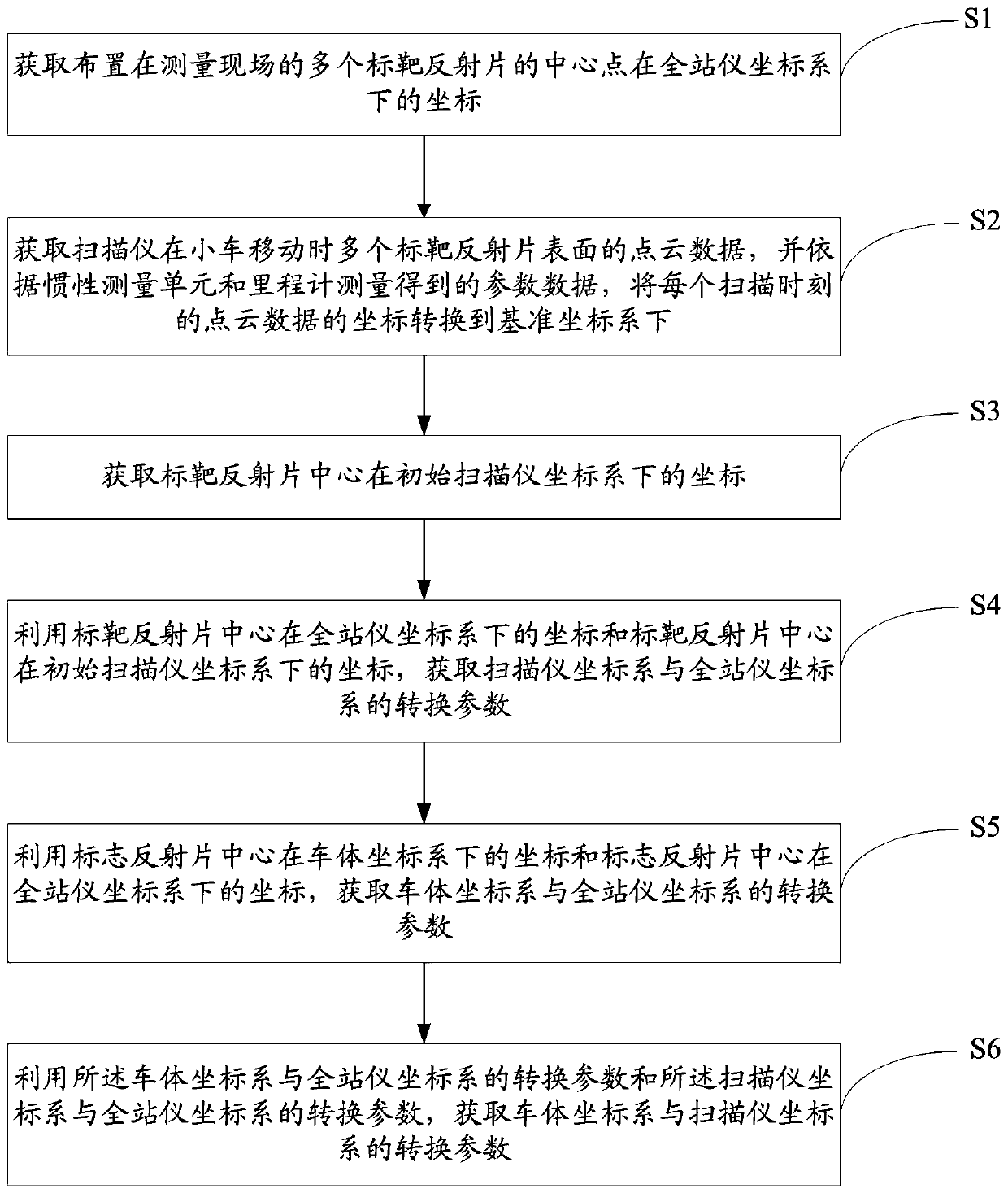
[0067] figure 2 It is a flowchart of a calibration method for a two-dimensional laser scanner according to an embodiment of the present invention.

[0068] see figure 2 , the two-dimensional laser scanner cali...


PUM


Abstract

The invention discloses a two-dimension laser scanner calibration method, a system and a device; the method comprises the following steps: obtaining coordinates of the central point of a target reflector under a total station coordinate system; obtaining point-cloud data of a plurality of target reflector surfaces of the scanner when a cart moves, and converting the point-cloud data coordinates under a reference coordinate system; obtaining coordinates of points with the reflection intensity greater than a preset threshold from the point-cloud data, and forming a point-set cluster according tothe distance between the point-cloud data with the reflection intensity greater than the preset threshold and neighboring point-cloud data; obtaining center of gravity coordinates of the point-set cluster, wherein the center of gravity coordinates refer to the coordinates of the target reflector center under an initial scanner coordinate system; obtaining conversion parameters between the scannercoordinate system and the total station coordinate system; obtaining the conversion parameters between a vehicle-body coordinate system and the total station coordinate system; obtaining the conversion parameters between the vehicle-body coordinate system and the scanner coordinate system. The method and system can improve the calibration precision, and can provide fast and real time effects.

Description

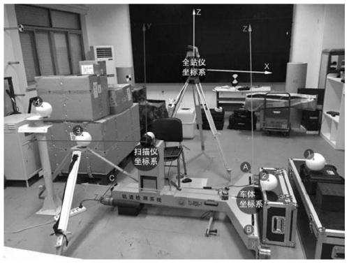
technical field [0001] The invention relates to the technical field of mobile measurement, in particular to a calibration method, system and device for a two-dimensional laser scanner. Background technique [0002] The ultimate goal of the mobile measurement system is to obtain point cloud data in a certain coordinate system. Since the generation of point clouds often involves the fusion of multiple sensors, one of the key problems that the mobile measurement system needs to solve is to calibrate different The measurement results of the sensors in the coordinate system are unified into a reference coordinate system. [0003] The laser scanner calibration of a typical mobile measurement system usually uses the following three coordinate systems: scanner coordinate system LC (Laser Coordinate), vehicle body coordinate system VC (Vehicle Coordinate) and total station coordinate system TC (Total Station Coordinate). At present, the commonly used two-dimensional scanner calibra...

Claims


Application Information

Patent Timeline
Patent Type & Authority Patents(China)
IPC IPC(8): G01B11/00G01C25/00
CPCG01B11/00G01B21/042G01C25/00
Inventor 孙海丽姚连璧王子轩张邵华
Owner CAPITAL NORMAL UNIVERSITY
Learn More