Structure and mounting method of flow measurement sensor based on transit time method

A measurement sensor and flow measurement technology, which is applied in the direction of measurement devices, measurement flow/mass flow, liquid/fluid solid measurement, etc., can solve the problem of precise positioning, directional installation of sensors, difficulty in installation, high cost, and high operational accuracy requirements. Advanced problems, to achieve the effect of reducing installation complexity and installation cost, easy online replacement, and improving installation accuracy

Active Publication Date: 2018-03-09
PHOTIME INSTR GUANGZHOU
View PDF4 Cites 8 Cited by
  • Summary
  • Abstract
  • Description
  • Claims
  • Application Information

AI Technical Summary

Problems solved by technology

[0006] However, in practical applications, the beam path that does not pass through the center of the pipe circle is generally only suitable for the production of small and medium-caliber pipeline flowmeters, which are installed and debugged in the factory. Larger-caliber flowmeters are produced or need to install insertion flowmeters on site. Under certain circumstances, it is very difficult to accurately locate and orientate the installation of sensors on the pipeline
For example, Germany's Siemens has introduced a dual-channel insertion sensor for on-site installation, which realizes a half-chord distance beam path and can obtain high measurement accuracy in a large flow range. However, the on-site

Method used


Image

  • Structure and mounting method of flow measurement sensor based on transit time method
  • Structure and mounting method of flow measurement sensor based on transit time method
  • Structure and mounting method of flow measurement sensor based on transit time method

Examples


Embodiment 1

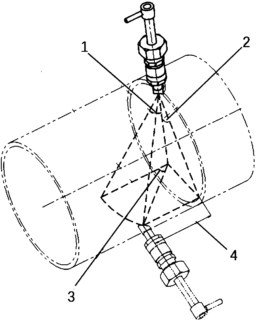
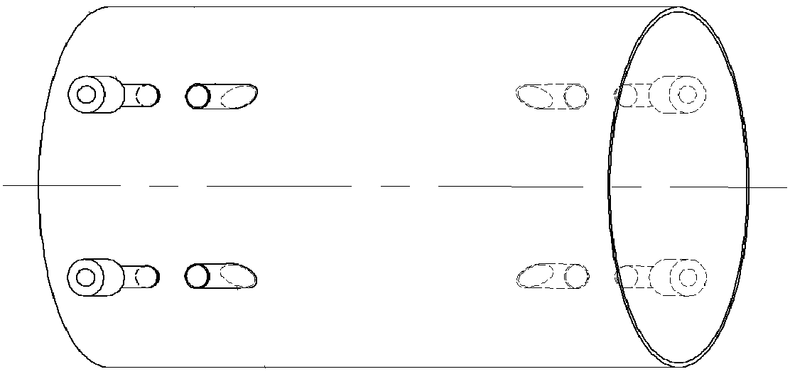
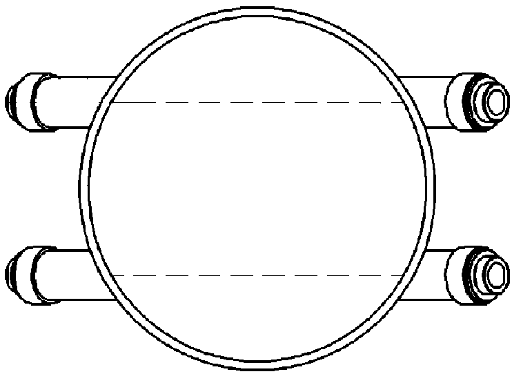
[0072] The on-site installation process of the existing dual-channel plug-in sensor introduced by Siemens is very complicated, such as figure 2 and image 3 As shown, it needs to weld a special inclined sleeve on the surface of the pipeline at the installation site to install the sensor, which requires high operation accuracy and high equipment cost. The invention does not need to weld a special inclined sleeve on the surface of the pipeline at the installation site, and the flow measurement sensor can be installed vertically on the pipeline wall only by punching holes in the ordinary pipe wall, which greatly reduces the installation complexity and installation complexity of the flow measurement sensor. cost.

[0073] Taking a flow measurement sensor based on the time-of-flight method in which the second included angle 2 is 30° and the emission beam is an acoustic wave as an example, a structure and an installation method of the flow measurement sensor of the present inventi...


PUM


Abstract

The invention discloses a structure and a mounting method of a flow measurement sensor based on a transit time method. The structure comprises first flow measurement sensors and second flow measurement sensors which are arranged pairwise and vertically mounted on the wall of a pipeline, wherein wave beam ends capable of transmitting and receiving wave beams are arranged at bottom ends of the firstflow measurement sensors and the second flow measurement sensors, and wave bean straight lines formed between first wave beam ends and second wave beam ends do not intersect with the axis of the pipeline, and the included angle formed by the wave beam straight lines and the axis of the pipeline is smaller than 90 degrees. The flow measurement sensors are vertically mounted on the wall of the pipeline, the mounting complexity and the mounting cost of the flow measurement sensors are reduced, besides, wave beam straight lines do not intersect with the axis of the pipeline, the included angle formed by the wave beam straight lines and the axis of the pipeline is smaller than 90 degrees, so that the effects of Reynolds numbers of fluids on measurement coefficients are reduced, and the high-flow-velocity multi-working-condition flow measurement accuracy is improved. The structure and the mounting method can be widely applied to the flow measurement field.

Description

technical field [0001] The invention relates to the field of flow measurement, in particular to a structure and installation method of a flow measurement sensor based on the time-of-flight method. Background technique [0002] Transit Time Ultrasonic Flow Measurement refers to the use of a pair of beam transducers to alternately (or simultaneously) send and receive beams, and calculate the flow velocity of the measured fluid by detecting the forward and reverse propagation time differences of the beams in the medium , and then calculate the flow rate by the flow rate. The beams that can be applied to flow measurement are acoustic, ultrasonic and light waves. [0003] Beam flowmeters have been applied in more and more occasions because they have no moving parts, long service life, high precision and good stability. field. Large-diameter beam flowmeters can be installed with flow measurement devices on existing pipelines by using field-insertable sensors, which can greatly ...

Claims


Application Information

Patent Timeline
IPC IPC(8): G01F1/66
CPCG01F1/661G01F1/667
Inventor 刘风华
Owner PHOTIME INSTR GUANGZHOU
Why Eureka
Try Eureka