Active tracking and positioning-based monitoring system

An active tracking and monitoring system technology, applied in positioning, closed-circuit television systems, radio wave measurement systems, etc., can solve problems such as geographical blind spots, inability to cover monitoring sites in real time, time monitoring blind spots, etc.

Inactive Publication Date: 2018-03-09
GUANGDONG POLYTECHNIC NORMAL UNIV
View PDF0 Cites 2 Cited by
  • Summary
  • Abstract
  • Description
  • Claims
  • Application Information

AI Technical Summary

Problems solved by technology

[0002] At present, the video monitoring of most anti-theft systems is fixed for one direction, and the monitoring is carried out by manually watching the video. There are geographical blind spots and the monitoring site cannot be covered.
Even if some video surveillance is equipped with a pan / tilt to obtain the video of the surveillance scene through periodic rotation, there are still monitoring blind spots in time, and it is impossible to cover the surveillance scene in real time

Method used


Image

  • Active tracking and positioning-based monitoring system
  • Active tracking and positioning-based monitoring system
  • Active tracking and positioning-based monitoring system

Examples


Embodiment

[0013] Below in conjunction with accompanying drawing, the implementation of the present invention is described in further detail:

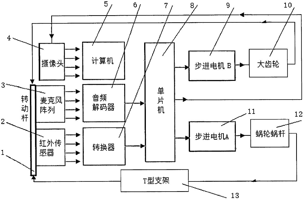
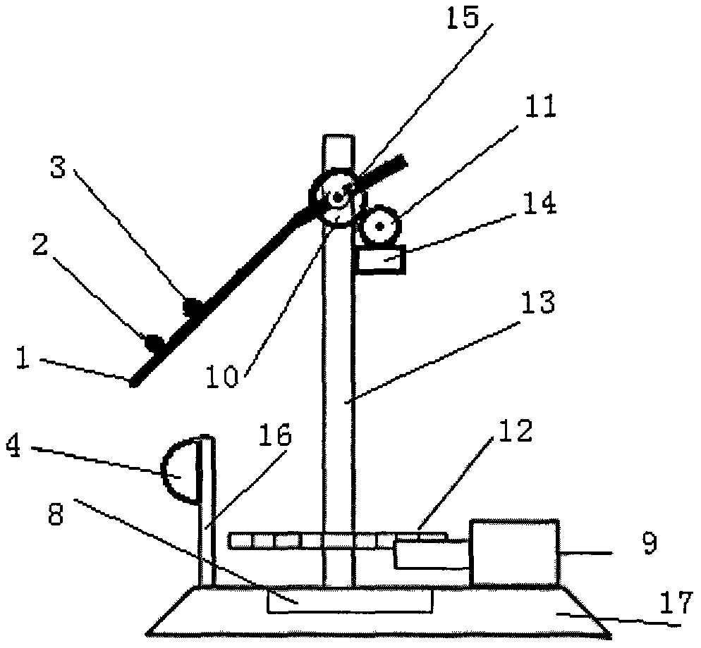
[0014] figure 1 It is the schematic diagram of the composition of the system, which consists of a rotating rod (1), an infrared sensor (2), a microphone array (3), a camera (4), a computer (5), an audio decoder (6), a converter (7), Single-chip microcomputer (8), stepping motor B (9), bull gear (10), stepping motor A (11), worm gear (12), T-shaped support (13) form.

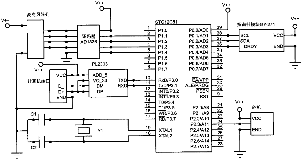
[0015] figure 2 Wiring diagram for the microphone array implementation of this system. Single-chip microcomputer (8) is connected with audio frequency decoder (6), and single-chip microcomputer (8) selects STC12C51 for use, and audio frequency decoder (6) selects AD1836 for use. The camera (4) selects SCC-C6475 high-definition night vision camera for use, comes with a cloud platform, and the single-chip microcomputer (8) outputs position information to control the camera to trac...


PUM


Abstract

The patent of the present invention is a monitoring system based on active tracking and positioning, which consists of a rotating rod, an infrared sensor, a camera, a microphone array, an audio decoder, a computer, a converter, a single-chip microcomputer, a stepping motor B, a large gear, and a stepping motor A , a worm gear, a T-shaped bracket, and a base, and an infrared sensor, a camera, and a microphone array are installed on the rotating rod. The large gear drives the rotating rod to rotate to change the inclination angle, the worm gear is installed at the lower end of the T-shaped bracket, and the motor drives the worm gear to drive the T-shaped bracket to rotate around the vertical axis to change the orientation of the camera. The microphone array is used to determine the spatial position of the sound source, and the infrared sensor is used to determine the spatial position of the human body. The single-chip microcomputer analyzes and processes the detection signal of the sensor, and then outputs the signal to control the stepping motor A and stepping motor B to realize the active tracking and positioning monitoring function.

Description

1. Technical field [0001] The invention patent is a monitoring system based on active tracking and positioning, especially a tracking and positioning monitoring system combining sound source and heat source, which belongs to the technical field of electronic monitoring. 2. Background technology [0002] At present, the video monitoring of most anti-theft systems is fixed for one direction, and the monitoring is carried out by manually watching the video. There are geographical blind spots and the monitoring site cannot be covered. Even if some video surveillance is equipped with a pan-tilt to obtain the surveillance site video through periodic rotation, there is still a monitoring blind spot in time, and the surveillance site cannot be covered in real time. 3. Contents of the invention [0003] The purpose of the present invention is to provide a tracking and positioning monitoring system based on the combination of sound source and heat source, which can realize the rapid...

Claims


Application Information

Patent Timeline
Patent Type & Authority Applications(China)
IPC IPC(8): G01S5/22G01J5/00H04N7/18
CPCG01S5/22G01J5/0025H04N7/18
Inventor 罗忠辉许锦川白路
Owner GUANGDONG POLYTECHNIC NORMAL UNIV
Why Eureka
Try Eureka