Spliced optical imaging system

An optical imaging system and splicing technology, applied in the optical field, can solve the problems of inability to effectively eliminate the stray light of the splicing seam, cannot meet the contrast, etc., achieve high splicing accuracy and contrast, suppress the generation of stray light, and meet the needs of use. Effect

Pending Publication Date: 2018-03-09
XIAN MICROMACH TECH CO LTD
View PDF0 Cites 5 Cited by
  • Summary
  • Abstract
  • Description
  • Claims
  • Application Information

AI Technical Summary

Problems solved by technology

[0005] The current mainstream splicing optical imaging system mainly uses a single PBS prism (polarization beam splitter) and a micro-display chip for imaging. Due to the imperfection of optical components and the secondary reflection inside a single PBS prism, the existing Although this type of splicing optical

Method used


Image

  • Spliced optical imaging system
  • Spliced optical imaging system

Examples


Embodiment Construction

[0020] In order to facilitate the understanding of the present invention, the present invention will be described more fully below with reference to the associated drawings. Preferred embodiments of the invention are shown in the accompanying drawings. The above are only preferred embodiments of the present invention, and are not intended to limit the patent scope of the present invention. Any equivalent structure or equivalent process conversion made by using the description of the present invention and the contents of the accompanying drawings, or directly or indirectly used in other related technical fields , are all included in the scope of patent protection of the present invention in the same way.

[0021] Unless otherwise defined, all technical and scientific terms used herein have the same meaning as commonly understood by one of ordinary skill in the technical field of the invention. The terminology used herein in the description of the present invention is only for ...


PUM


Abstract

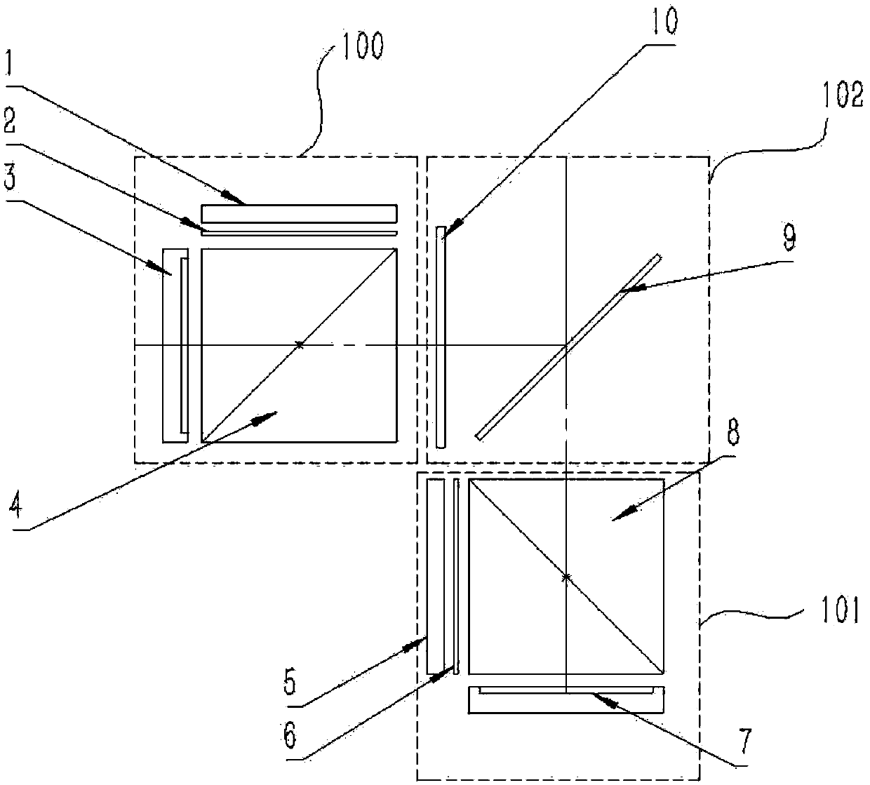
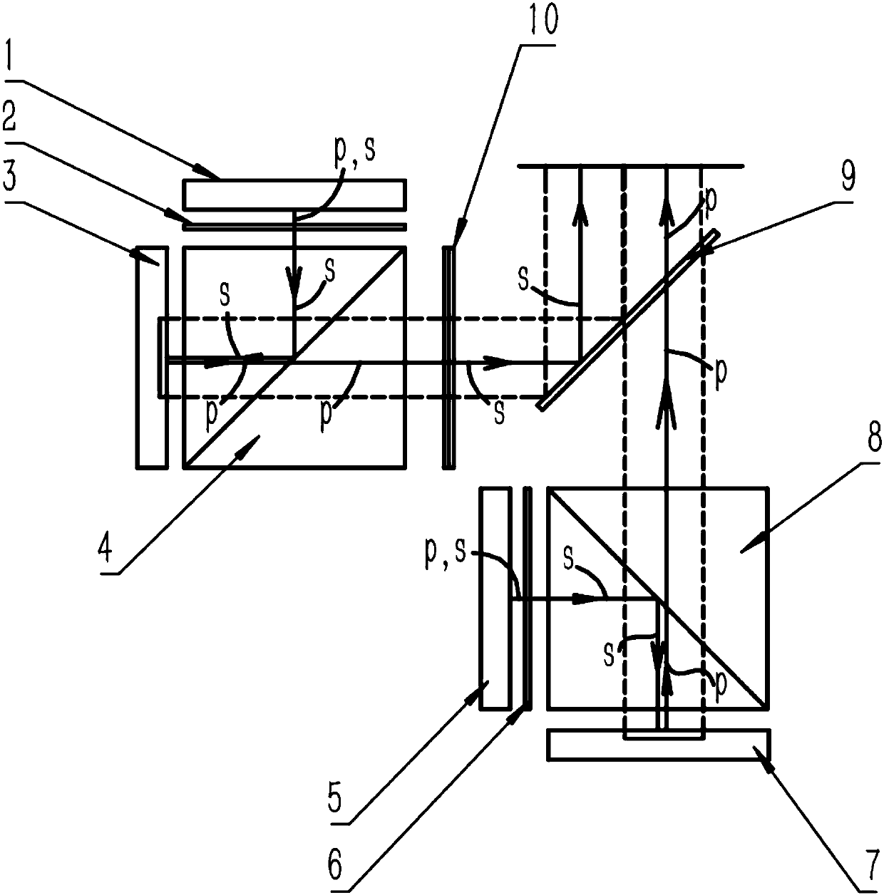
The present invention provides a spliced ​​optical imaging system, which comprises: a first display group (100) with a first micro-display chip arranged along a first optical path; a second display group (100) with a second micro-display chip arranged along a second optical path; A display group (101) and a polarization combination module (102) located at the intersection of the first optical path and the second optical path, the first optical path and the second optical path are perpendicular to each other, and the first display group The image displayed by (100) and the image displayed by the second display group (101) are imaged on the same imaging plane after passing through the polarization combining module (102). The splicing optical imaging system can effectively realize the seamless splicing of confocal planes and other frames, can meet the use requirements of larger arrays, and has higher splicing accuracy and contrast.

Description

technical field [0001] The invention relates to the field of optical technology, in particular to a spliced ​​optical imaging system applied to a dynamic star simulator. Background technique [0002] With the gradual development and improvement of the aerospace field and the improvement of ground supporting detection and calibration equipment technology, the dynamic star simulator is used as a calibration inspection equipment for simulating starry sky images in this type of equipment, and its accuracy and resolution are also developing day by day. . [0003] The stitching high-resolution optical imaging system is the core display module in the dynamic star simulator, and its stitching accuracy, resolution and contrast directly determine the performance of the dynamic star simulator. [0004] Due to the production and processing limitations of micro-display devices such as TFT-LCD, DMD, and LCOS in the field of micro-displays, it is difficult to produce large-scale, high-res...

Claims


Application Information

Patent Timeline
IPC IPC(8): G02B27/28
CPCG02B27/283
Inventor 王啸腾胡加杰王华杨小君
Owner XIAN MICROMACH TECH CO LTD
Why Eureka
Try Eureka