Drilling machine lubricating system

A technology for lubrication system and drilling machine, which is applied in the direction of engine lubrication, maintenance and safety accessories, mechanical equipment, etc. It can solve the problems of complex structure and poor lubrication effect, and achieve the effect of reasonable and simple structure, convenient adjustment and easy lubrication

Pending Publication Date: 2018-03-13
巩义市巧匠人机械设备制造有限公司
View PDF0 Cites 0 Cited by
  • Summary
  • Abstract
  • Description
  • Claims
  • Application Information

AI Technical Summary

Problems solved by technology

[0002] With the development of the mechanical processing industry, the update of mechanical equipment is also carried out continuously. In the mechanical processing industry, the lubrication system is indispensable. The function of the lubrication system is to reduce the wear and tear of the machine; now on the market, lubrication There are many kinds of systems, all of which have their own characteristics. Although there are so many lubrication systems, there are still more or less deficiencies, such as complex structure and poor lubrication effect. In view of these deficiencies, it is necessary to develop A lubricating system with good lubricating effect, reasonable and simple structure, convenient adjustment, and preventing clogging; therefore, it is of great significance to develop a drilling machine lubricating system with good lubricating effect, reasonable and simple structure, convenient adjustment, and preventing clogging

Method used


Image

  • Drilling machine lubricating system
  • Drilling machine lubricating system

Examples


Embodiment 1

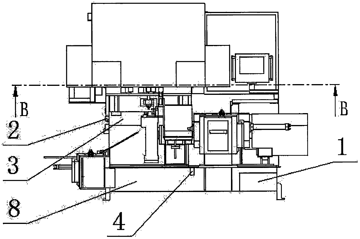
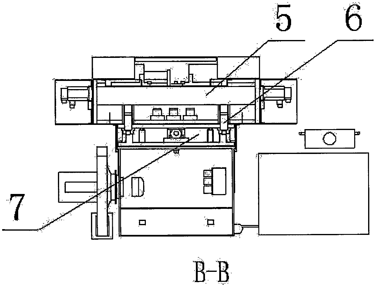
[0012] Such as Figure 1-2 As shown, a drilling machine lubrication system, which includes a lubricating oil tank 1, the left side of the lubricating oil tank 1 is provided with an equipment base 8, the upper part of the equipment base 8 is provided with an oil return pipeline channel 4, the equipment An oil receiving tank A3 is arranged above the base 8, an oil return nozzle 2 is arranged on the left side of the oil receiving tank A3, an oil receiving pan 5 is arranged above the oil receiving tank A3, and an oil receiving pan 5 is arranged below the described oil receiving pan 5 There is an oil guide groove 6, and the lower side of the oil guide groove 6 is provided with an oil receiving groove B7.

[0013] The present invention uses the interaction of lubricating oil tank, oil return nozzle, oil return pipeline channel, oil receiving pan, oil guiding groove, oil receiving groove A and oil receiving groove B to complete the lubrication of the equipment, and the lubricating oi...

Embodiment 2

[0015] Such as Figure 1-2 As shown, a drilling machine lubrication system, which includes a lubricating oil tank 1, the left side of the lubricating oil tank 1 is provided with an equipment base 8, the upper part of the equipment base 8 is provided with an oil return pipeline channel 4, the equipment An oil receiving tank A3 is arranged above the base 8, an oil return nozzle 2 is arranged on the left side of the oil receiving tank A3, an oil receiving pan 5 is arranged above the oil receiving tank A3, and an oil receiving pan 5 is arranged below the described oil receiving pan 5 There is an oil guide groove 6, and the lower side of the oil guide groove 6 is provided with an oil receiving groove B7, using the lubricating oil tank 1, the oil return nozzle 2, the oil return pipeline channel 4, the oil receiving plate 5, the oil guide groove 6, the oil receiving groove A3 and the oil receiving groove The mutual cooperation of B7 completes the principle of equipment lubrication. ...


PUM


Abstract

The invention relates to a drilling machine lubrication system, which includes a lubricating oil tank, an equipment base is arranged on the left side of the lubricating oil tank, an oil return pipeline channel is arranged on the upper part of the equipment base, and a An oil receiving tank A, an oil return nozzle is provided on the left side of the oil receiving tank A, an oil receiving pan is provided above the oil receiving tank A, and an oil guiding groove is arranged below the oil receiving pan, and the oil guiding tank An oil receiving groove B is arranged on the lower side of the oil tank; the invention has the advantages of good lubricating effect, reasonable and simple structure, pollution prevention, convenient adjustment and blockage prevention.

Description

technical field [0001] The invention belongs to the technical field of mechanical processing equipment, and in particular relates to a drilling machine lubrication system. Background technique [0002] With the development of the mechanical processing industry, the update of mechanical equipment is also carried out continuously. In the mechanical processing industry, the lubrication system is indispensable. The function of the lubrication system is to reduce the wear and tear of the machine; now on the market, lubrication There are many kinds of systems, all of which have their own characteristics. Although there are so many lubrication systems, there are still more or less deficiencies, such as complex structure and poor lubrication effect. In view of these deficiencies, it is necessary to develop A lubricating system with good lubricating effect, reasonable and simple structure, convenient adjustment and anti-clogging prevention; therefore, it is of great significance to d...

Claims


Application Information

Patent Timeline
Patent Type & Authority Applications(China)
IPC IPC(8): B23Q11/12F16N7/38
CPCB23Q11/121F16N7/38
Inventor 孙利峰
Owner 巩义市巧匠人机械设备制造有限公司
Why Eureka
Try Eureka