
Composite spinneret plate

A composite spinneret and spinneret technology, which is applied in the field of spinning equipment, can solve the problem that the same board double special-shaped fiber and the same board multi-double special-shaped fiber cannot be smoothly spun and processed, and achieve smooth and stable spinning and high extrusion speed. consistent effect

Inactive Publication Date: 2018-03-13
JIANGSU HENGLI CHEM FIBER
View PDF7 Cites 12 Cited by
  • Summary
  • Abstract
  • Description
  • Claims
  • Application Information

AI Technical Summary

Problems solved by technology

[0007] The purpose of the present invention is to overcome the problem in the prior art that the same board double special-shaped fiber and the same board multi-double special-shaped fiber cannot be successfully spun and processed, and provide a method that can ensure the same board double special-shaped fiber and the same board multi-double special-shaped fiber to be spun smoothly. Composite spinneret for wire processing

Method used


Image

  • Composite spinneret plate
  • Composite spinneret plate
  • Composite spinneret plate

Examples


Embodiment 1

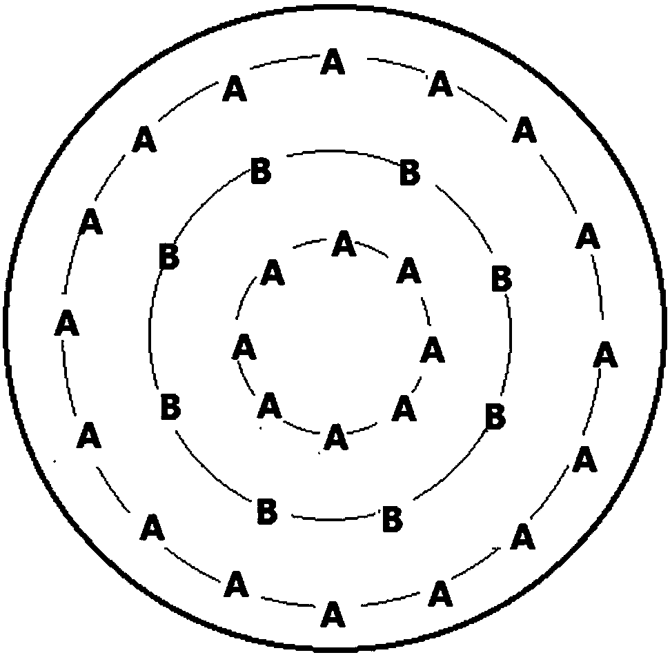
[0037] A composite spinneret on which two different spinneret holes A and B are provided at the same time. The ratio of the length of the micro-holes of the spinneret A to the spinneret B is equal to the spinneret A and the spinneret The product of the ratio of the equivalent diameter of the hole B and the coefficient K and the ratio of the consistency coefficient of the material flowing through the orifice B and the material flowing through the orifice A, the equivalent diameter is the cross-sectional area of ​​the orifice and the cross-sectional circumference The ratio of length, where the coefficient K ranges from 0.97 to 1.03, the micropore length of spinneret A or B is 0.30 to 2.08mm, and the equivalent diameter of spinneret A or B is 0.15 to 0.52mm. Spinning hole A and spinning hole B are arranged in concentric circles on the spinneret, and the center or circumscribed circle center of spinning hole A and spinning hole B are located on concentric circles with equal interva...

Embodiment 2

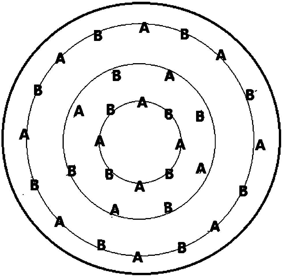
[0039] A composite spinneret. The basic structure is the same as that of Example 1. The difference is that the shape and arrangement of the spinneret holes are different. figure 2 As shown, the same ring on the spinneret contains both spin hole A and spin hole B, wherein the number ratio of spin hole A to spin hole B is 1:1, and the shape of spin hole A is triangle , The shape of the spinneret hole B is in-line.

Embodiment 3

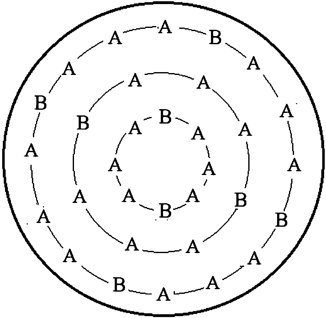
[0041] A composite spinneret. The basic structure is the same as that in Example 2. The difference is that the spinneret hole shape and arrangement are different. The schematic diagram is as follows image 3 As shown, the same ring on the spinneret contains both spin hole A and spin hole B, wherein the number ratio of spin hole A to spin hole B is 3:1, and the shape of spin hole A is five Leaf shape, the shape of the spinneret B is circular.


PUM

PropertyMeasurementUnit
lengthaaaaaaaaaa
diameteraaaaaaaaaa

Abstract

The invention relates to a composite spinneret plate. Two different spinneret orifices A and B are formed in the spinneret plate, the micropore length ratio of the spinneret orifices A and B is equalto the arithmetic product of the equivalent diameter ratio of the spinneret orifices A and B, the coefficient K and the consistency coefficient ratio of materials flowing through the spinneret orifices B and A, the equivalent diameter is the ratio of the cross-sectional area of the spinneret orifices to the cross-sectional perimeters of the spinneret orifices, the coefficient K is 0.97-1.03, the micropore length of the spinneret orifices A or B is 0.30-2.08mm, and the equivalent diameter is 0.15-0.52mm. According to the composite spinneret plate, by setting the micropore lengths, the cross-sectional area and the cross-sectional perimeters of the two spinneret orifices and establishing a certain relationship among the sizes of the two spinneret orifices and the consistency coefficient of the materials flowing through the two spinneret orifices, the pressure drop of polymer melts passing different spinneret orifices of the same spinneret plate is basically the same, so that the extrusionspeed of the melts from the spinneret orifices is basically consistent, and smooth spinning can be realized.

Description

Technical field [0001] The invention belongs to the field of spinning equipment and relates to a composite spinneret. Background technique [0002] Since most ordinary fibers have a certain degree of performance defects, and the fiber profile technology can increase the added value of the fiber, thereby improving the performance of the fiber. Therefore, in recent years, the fiber profile technology has been researched by researchers. Hot spot. Fiber profile technology mainly includes fiber cross-section profile profile, fiber three-dimensional crimping and fiber shrink profile profile. The material and shape characteristics of the fiber affect the performance of the fiber. The arrangement of the fiber and the fiber in the yarn affects the performance of the yarn. The arrangement of the yarn and the yarn in the fabric affects the performance of the fabric. Therefore, the shape feature of the fiber affects the yarn. And the nature of fabric performance, fibers with different cros...

Claims


Application Information

Patent Timeline
Patent Type & Authority Applications(China)
IPC IPC(8): D01D4/02D01D5/253D01D5/24
CPCD01D4/02D01D5/24D01D5/253
Inventor 王丽丽李文刚王山水
Owner JIANGSU HENGLI CHEM FIBER
Learn More