Heat pump appliance capable of defrosting without reversing refrigerant cycle

A refrigerant and refrigerant circuit technology, applied in the field of heat pump equipment, can solve problems such as temperature reduction, reduction of indoor thermal comfort, and reduction of comfort

Inactive Publication Date: 2018-03-13
威能有限公司
View PDF5 Cites 1 Cited by
  • Summary
  • Abstract
  • Description
  • Claims
  • Application Information

AI Technical Summary

Problems solved by technology

[0004] However, in the traditional defrosting mode, the heating of the room must be stopped, and in addition, since the internal heat exchanger is now used as an evaporator, it extracts heat from the room air. Thermal comfort, and the temperature of the internal plate heat exchanger may also drop below 0°C

Method used


Image

  • Heat pump appliance capable of defrosting without reversing refrigerant cycle
  • Heat pump appliance capable of defrosting without reversing refrigerant cycle
  • Heat pump appliance capable of defrosting without reversing refrigerant cycle

Examples


Embodiment Construction

[0022] The present invention will be described in detail below in conjunction with various embodiments shown in the drawings. However, these embodiments do not limit the present invention, and any structural, method, or functional changes made by those skilled in the art according to these embodiments are included in the protection scope of the present invention.

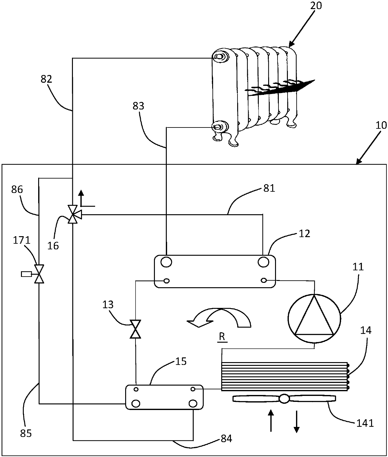
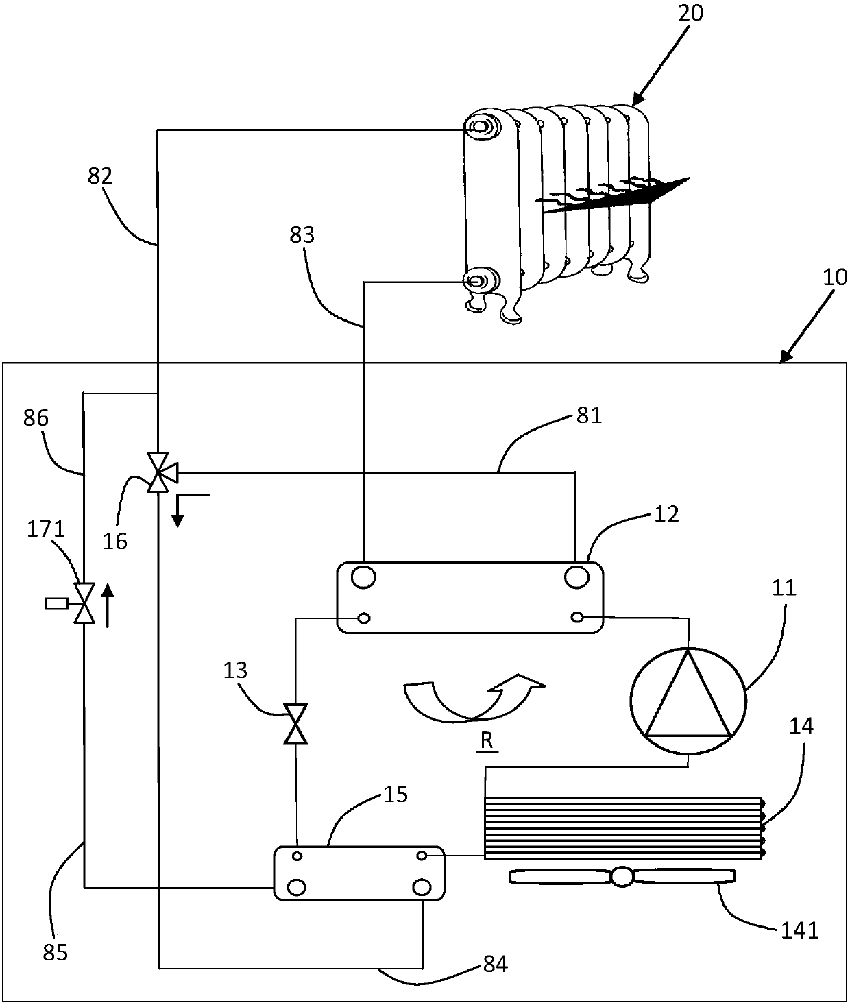
[0023] refer to Figure 1A As shown, a heat pump device 10 in the first embodiment of the present invention operates in a heating mode for heating the air inside a building. The heat pump device 10 includes a refrigerant circuit R, a first fluid control valve 16 , and a second fluid control valve 171 . The refrigerant circuit R generally comprises a compressor 11 , a first heat exchanger 12 operating as a condenser, a throttling device 13 and a second heat exchanger 14 operating as an evaporator. Compressor 11 typically uses electricity to compress the refrigerant from a low pressure gas state to a high pressure ga...


PUM


Abstract

The present invention discloses a heat pump appliance including a refrigerant circuit operable in a plurality of modes to transfer heat between an exterior atmosphere and an interior atmosphere via arefrigerant. The refrigerant circuit includes a compressor for compressing the refrigerant, a first heat exchanger for transferring heat between the refrigerant and the interior atmosphere, a throttling device for lowering the pressure of the refrigerant, and a second heat exchanger for transferring heat between the refrigerant and the exterior atmosphere. Wherein, the first heat exchanger operates as a condenser to cool the refrigerant in a heating mode and operates as an evaporator to vaporize the refrigerant in a cooling mode, the second heat exchanger operates as an evaporator in the heating mode. The appliance further includes a third heat exchanger connected in the refrigerant circuit and positioned near the second heat exchanger. The third heat exchanger is selectively hydraulicallycommunicated with the first heat exchanger for transferring heat released by the refrigerant at the first heat exchanger to the refrigerant at the third heat exchanger in a defrosting mode, thereby pre-heating the refrigerant entering the second heat exchanger. In this way, the heat energy condensed in the first heat exchanger can be partially used to defrost the coil-type second heat exchanger,so there is no need to reverse the refrigerant cycle in the defrosting mode. Accordingly, heating demands of users can be ensured on defrosting, moreover, the freezing risk of the interior plate-to-plate heat exchanger can be reduced, furthermore, the noise generated in reversing of the refrigerant cycle can be avoided.

Description

technical field [0001] The present invention relates to a heat pump device, in particular to a heat pump device capable of defrosting an outdoor heat exchanger coil without reversing the refrigerant cycle. Background technique [0002] Heat pumps are well known for heating and / or cooling the air inside buildings. A typical heat pump usually has a refrigerant circuit including a compressor, condenser, expansion valve and evaporator. A heat transfer medium (often called refrigerant) circulates in the refrigerant circuit to transfer heat from a first location to a second location. For an air-to-air heat pump, during heating mode operation, outdoor air is used as the heat source, the outdoor heat exchanger is used as the evaporator, and the indoor heat exchanger is used as the condenser. Thus, the refrigerant absorbs heat from the outside atmosphere through the evaporator and releases heat to the inside air through the condenser. Heat pumps can also be designed to reverse thi...

Claims


Application Information

Patent Timeline
IPC IPC(8): F25B30/02F25B47/02F25B41/06F25B49/02F25B43/00F25B41/20F25B41/31
CPCF25B30/02F25B43/006F25B47/02F25B49/02F25B41/31F25B13/00F25B2313/003F25B2313/004F25B2313/0254F25B2400/05F24D3/18F24D2200/24Y02B30/12Y02B30/52
Inventor 圣地亚哥·锡德·克鲁兹
Owner 威能有限公司
Why Eureka
Try Eureka