Compressor waste heat recovery defrosting system based on phase change energy storage and working method

A waste heat recovery and phase change energy storage technology, which is applied to the operation mode of machines, refrigerators, mechanical equipment, etc., can solve the problems of inability to realize the recovery and utilization of waste heat from compressors, the inability of the system to supply heat to the room, and the reduction of indoor heat supply, etc. Problems, to achieve the effect of reducing indoor temperature fluctuations, reducing pipeline layout, and reducing heat loss

Inactive Publication Date: 2021-10-22
XI AN JIAOTONG UNIV
View PDF7 Cites 0 Cited by
  • Summary
  • Abstract
  • Description
  • Claims
  • Application Information

AI Technical Summary

Problems solved by technology

The reverse cycle defrosting method reverses the flow of refrigerant through the reversing of the four-way valve, and switches the compressor from heating to cooling. Therefore, when defrosting is running, the system cannot supply heat to the room, but from the room. Heat absorption, lowering the indoor temperature and affecting indoor comfort
The hot gas bypass defrosting method is to directly introduce a part of the high-temperature and high-pressure refrigerant discharged from the compressor into the outdoor heat exchanger for defrosting. Although it does not need to change the direction of the four-way valve, it also reduces the indoor heat supply and the defrosting time. Relatively long, can not realize the recovery of compressor waste heat

Method used


Image

  • Compressor waste heat recovery defrosting system based on phase change energy storage and working method
  • Compressor waste heat recovery defrosting system based on phase change energy storage and working method
  • Compressor waste heat recovery defrosting system based on phase change energy storage and working method

Examples


Embodiment Construction

[0019] The present invention will be described in further detail below in conjunction with the accompanying drawings and specific embodiments.

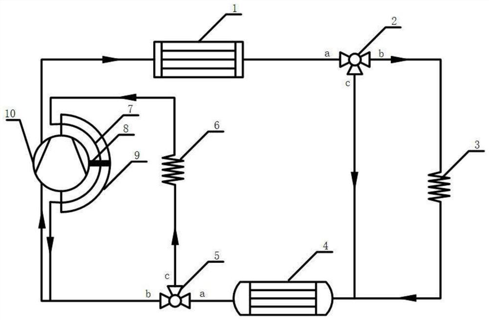
[0020] refer to figure 1 It is a structural connection schematic diagram of a compressor waste heat recovery and defrosting system based on phase change energy storage in the present invention. The system includes: indoor heat exchanger 1, No. 1 three-way valve 2, No. 1 throttle valve 3, outdoor heat exchanger Heater 4, No. 2 three-way valve 5, No. 2 throttle valve 6, heat transfer pipe 7, electric heater 8, phase change heat storage device 9, compressor 10. The heat transfer tube 7 and the electric heater 8 are arranged inside the phase change heat storage 9 . Such as Figure 4 As shown, the electric heater 8 is a finned electric heater

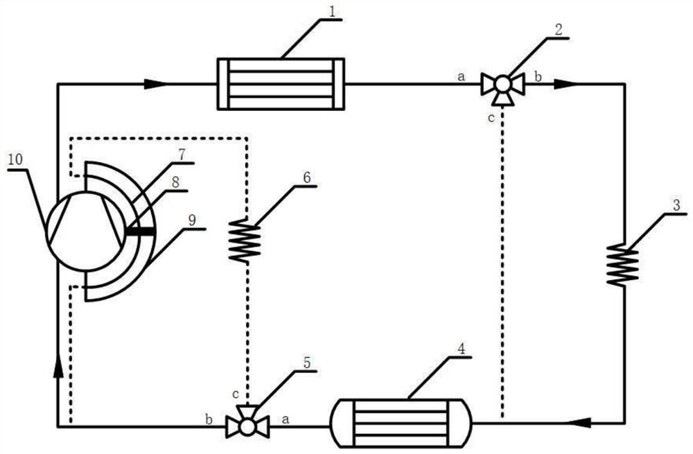
[0021] refer to figure 2 It is a schematic diagram of the heating mode principle of a compressor waste heat recovery defrosting system based on phase change energy storage in the present invent...


PUM


Abstract

The invention discloses a compressor waste heat recovery defrosting system based on phase change energy storage and a working method. The system is composed of an indoor heat exchanger, a first three-way valve, a first throttling valve, an outdoor heat exchanger, a second three-way valve, a second throttling valve, a heat transfer pipe, an electric heater, a phase change heat reservoir and a compressor. By means of opening and closing of the three-way valve, the indoor and outdoor heat exchangers serve as condensers at the same time, the phase change heat reservoir absorbs waste heat of the compressor and then serves as an evaporator to form a new defrosting system; when heat stored by the phase-change material is not enough for defrosting, the electric heater works to ensure that a refrigerant at an outlet of the phase change heat reservoir is superheated steam, so that heat supply and defrosting are carried out at the same time; the waste heat of the shell of the compressor is fully utilized, and the frosting problem in the low-temperature environment in the middle-south region is solved; the phase change heat reservoir serves as an evaporator, so that reversing of the four-way valve is avoided, indoor temperature fluctuation is reduced, pipeline arrangement is reduced, the heat loss is reduced, and then better heating and defrosting effects are achieved.

Description

technical field [0001] The invention relates to the field of compressor waste heat recovery, in particular to a compressor waste heat recovery defrosting system and working method based on phase change energy storage. Background technique [0002] As an important power source, compressors are widely used in steel, metallurgy, textile, chemical and other industrial fields. However, about 15% of the electrical energy consumed by the compressor is converted into heat energy and dissipated to the surrounding environment through shell convection and conduction. , resulting in a large amount of energy waste. In order to achieve the goals of "carbon peak" and "carbon neutrality", it is particularly important to reduce industrial energy consumption and promote energy saving of compressors. In the air conditioning system, the compressor will generate a lot of shell heat when it works. The temperature of the shell is often above 60°C, and the outlet temperature of the refrigerant is ...

Claims


Application Information

Patent Timeline
Patent Type & Authority Applications(China)
IPC IPC(8): F25B47/02F25B29/00F25B41/20F25B39/00F25B41/30F25B49/02
CPCF25B47/02F25B29/003F25B41/20F25B39/00F25B41/30F25B49/02
Inventor 陶于兵吕邹晨余银生王宛莹常浩
Owner XI AN JIAOTONG UNIV
Why Eureka
Try Eureka