
High-precision positioning device and high-precision positioning assisting method

A positioning device and high-precision technology, applied in the direction of measuring devices, instruments, etc., can solve the problems of aggravated wear and can not solve the problem of low-speed and large-load precision positioning

Pending Publication Date: 2018-03-13
HANGZHOU HANGYAN ENVIRONMENT TECH CO LTD +1
View PDF12 Cites 4 Cited by
  • Summary
  • Abstract
  • Description
  • Claims
  • Application Information

AI Technical Summary

Problems solved by technology

Direct drive technology is often used in high-speed and small-load applications, and cannot solve the problem of precision positioning at low-speed and large loads; while pre-tightening technology can only reduce the error of the screw and the bearing itself, often cannot reduce the error of other links, and the pre-tightening technology will increase its wear and tear

Method used


Image

  • High-precision positioning device and high-precision positioning assisting method
  • High-precision positioning device and high-precision positioning assisting method
  • High-precision positioning device and high-precision positioning assisting method

Examples


Embodiment Construction

[0024] Embodiments of the present invention will be described below based on the drawings.

[0025] Structure of high precision positioning device

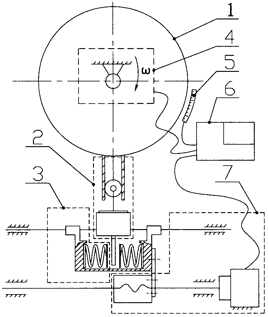
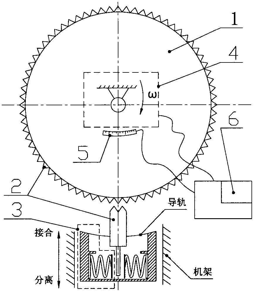
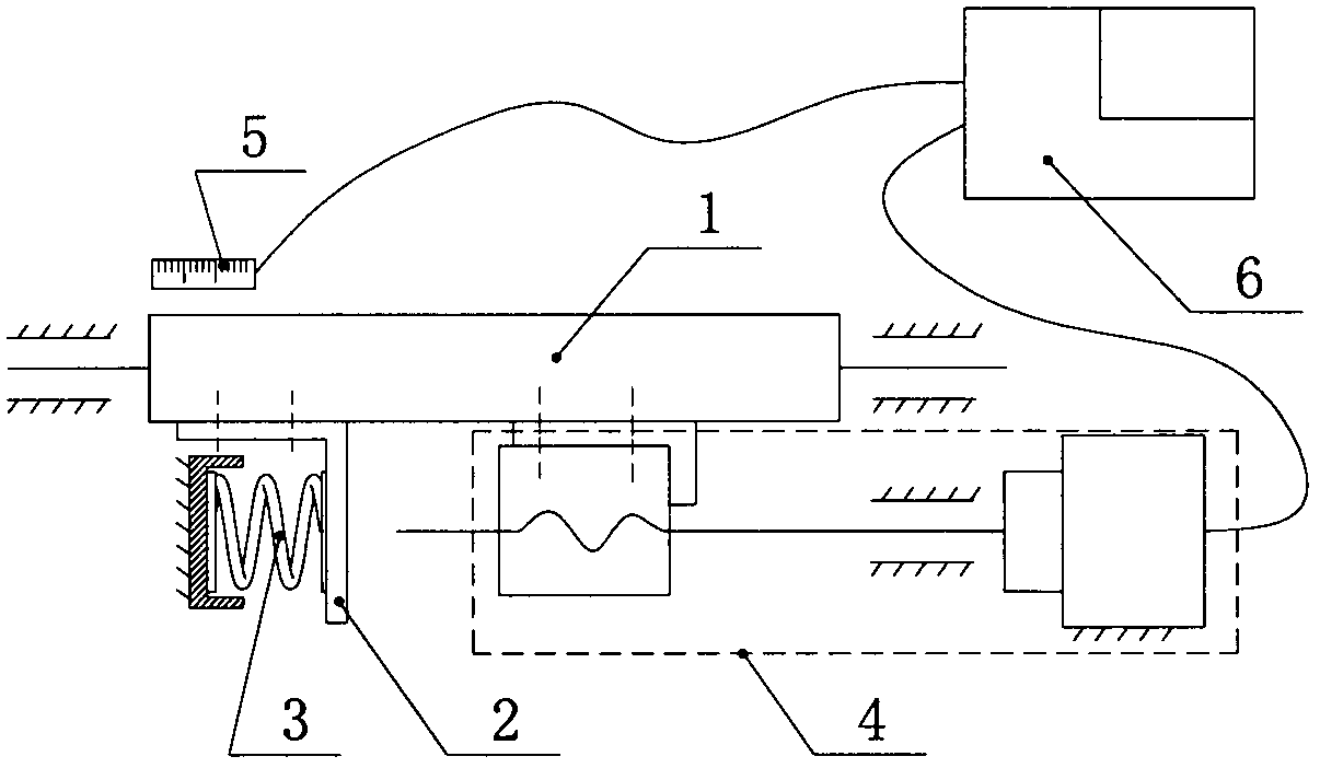
[0026] The first structural schematic diagram of a high-precision positioning device of the present invention is as follows: figure 1 As shown, it is applied to small-angle rotary indexing occasions; the second structural schematic diagram of a high-precision positioning device of the present invention is shown in figure 2 As shown, the elastic damper (3) can move radially along the worktable (1) under the action of an external force (the external force can be electromagnetic force, hydraulic pressure, etc.), and the radial movement makes the elastic damper (3) and The workbench (1) produces a clutch action, which makes the second structure applicable to large-angle rotary indexing occasions; the third structural schematic diagram of a high-precision positioning device of the present invention is as follows image 3 As shown, i...


PUM


Abstract

The invention discloses a high-precision positioning device, and the device is provided with a workbench, a blocking apparatus, an elastic damper, a drive apparatus, a terminal position detection apparatus, and a controller. The workbench makes linear motion or angular motion under the action of a driving force, and is used for the high-precision positioning of an external load. The terminal position detection apparatus is used for feeding back the position of the workbench. The drive apparatus is provided with a motor. The driver controls the drive apparatus to operate, and enables the workbench to reach a target position. The blocking device is directly or indirectly connected to the workbench. When the workbench gets close to the target position, a force applied by the drive apparatus to the workbench is a first direction force, and a force applied by the elastic damper to the workbench through the blocking apparatus is a second direction force, wherein the first direction force andthe second direction force are mutually a driving force and a resisting force. The first and second direction forces exist at the same time, thereby facilitating the reduction of a reverse gap and apositioning error caused by an inertia force, and improving the positioning precision of the workbench. The invention also discloses a high-precision positioning assisting method for the device.

Description

technical field [0001] The invention relates to a high-precision positioning device and a high-precision positioning auxiliary method, belonging to the field of high-precision positioning, especially the field of large-load precision positioning. Background technique [0002] Precision positioning devices include linear displacement positioning devices and rotary indexing devices. Linear displacement positioning devices are commonly used in linear displacement platforms, CNC gantry milling machines, etc., and their common driving methods are motor + reducer + screw. Rotary indexing devices are commonly found in indexing plates, indexing heads, rotary tables, etc., and their common driving methods are motor + reducer + worm gear. It is well known that due to the inevitable existence of various gaps between various transmission parts, the existence of these gaps often reduces the positioning accuracy of the precision positioning device. In order to improve the positioning ac...

Claims


Application Information

Patent Timeline
Patent Type & Authority Applications(China)
IPC IPC(8): G01B21/00
CPCG01B21/00
Inventor 叶荣伟徐华勒汤龙舟
Owner HANGZHOU HANGYAN ENVIRONMENT TECH CO LTD
Learn More