Optical system with projection and visual functions

An optical system and functional technology, applied in the field of optical systems, can solve problems such as poor user experience and head-mounted visual devices without projection functions, and achieve the effects of simple structure, improved user experience, and convenient use

Pending Publication Date: 2018-03-13
BEIJING LLVISION TECH CO LTD
View PDF0 Cites 4 Cited by
  • Summary
  • Abstract
  • Description
  • Claims
  • Application Information

AI Technical Summary

Problems solved by technology

[0004] The present application provides an optical system with projection and visual functions, which is used to solve the problem that head-mounted visual devices do not have projection functions and poor user experience in the prior art

Method used


Image

  • Optical system with projection and visual functions
  • Optical system with projection and visual functions
  • Optical system with projection and visual functions

Examples


Embodiment Construction

[0040] In the description of this specification, descriptions referring to the terms "one embodiment", "a specific embodiment", "some embodiments", "for example", "examples", "specific examples", or "some examples" etc. mean It means that the specific features, structures or characteristics described in conjunction with the embodiment or example are included in at least one embodiment or example of the present application. In this specification, schematic representations of the above terms do not necessarily refer to the same embodiment or example. Furthermore, the described specific features, structures or characteristics may be combined in any suitable manner in any one or more embodiments or examples. The sequence of steps involved in each embodiment is used to schematically illustrate the implementation of the present application, and the sequence of steps therein is not limited and can be appropriately adjusted as required.

[0041] The exemplary embodiments and descript...


PUM


Abstract

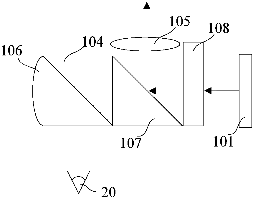
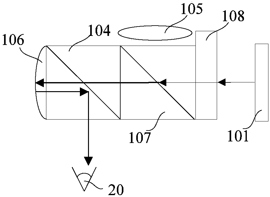
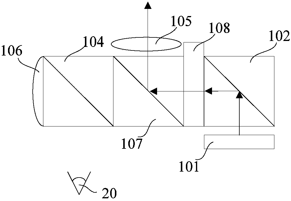
The application provides an optical system with projection and visual functions. The optical system, which is arranged on a head-mounted device, includes a display module, a second polarized beam splitter prism, a third polarized beam splitter prism, a projection lens group, a reflection lens group and a liquid crystal box. The liquid crystal box is fixedly arranged between the display module andthe third polarized beam splitter prism. The second polarized beam splitter prism is arranged on the side of the third polarized beam splitter prism away from the liquid crystal box. The reflection lens group is arranged on the side of the second polarized beam splitter prism away from the third polarized beam splitter prism. The projection lens group is arranged on the side of the third polarizedbeam splitter prism away from the human eyes. By adding the liquid crystal box, switching between the projection and visual functions can be realized, and users are enabled to see outside images clearly. The optical system has the characteristics of simple structure and convenience of use. A projection function is integrated into the head-mounted optical system, and the user experience can be improved.

Description

technical field [0001] The present application relates to the field of head-mounted visual devices, in particular to an optical system with projection and visual functions applied to head-mounted devices. Background technique [0002] The optical system of a head mounted display (HMD) in the prior art includes a display, a collimating lens and a reflective surface. Displays, such as LCD, OLED, LCOS, etc., emit different lights according to different display images, image them at infinity through collimating lenses, and then reflect the light emitted by the display into people's eyes through the reflective surface. [0003] However, the head-mounted video device in the prior art has a single function, which is only for individuals to watch the content played by the display in the head-mounted video device, and does not have a sharing (projection) function. In view of the limited size of the head-mounted device, it is difficult to add a new optical path to realize the project...

Claims


Application Information

Patent Timeline
IPC IPC(8): G02B27/01
CPCG02B27/017G02B27/0172
Inventor 吴斐
Owner BEIJING LLVISION TECH CO LTD
Why Eureka
Try Eureka