Equipment for laying cable on sea

A kind of equipment and cable laying technology, applied in the field of offshore cable laying equipment, can solve problems such as cable curling

Pending Publication Date: 2018-03-13
YANTAI UNIV
View PDF0 Cites 5 Cited by
  • Summary
  • Abstract
  • Description
  • Claims
  • Application Information

AI Technical Summary

Problems solved by technology

The cable laying equipment in the prior art does not have the function of fixing the head end of the laid cable, so that th

Method used


Image

  • Equipment for laying cable on sea
  • Equipment for laying cable on sea

Examples


Embodiment Construction

[0013] The present invention will be further described below in conjunction with the accompanying drawings and embodiments.

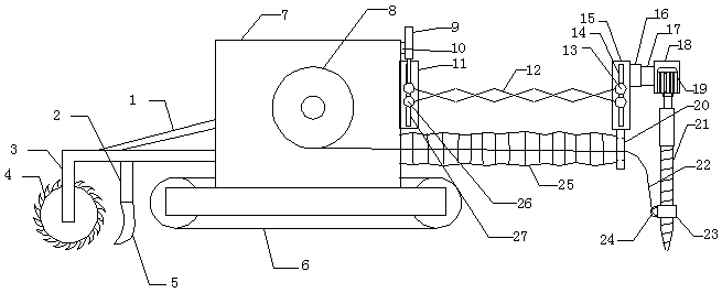
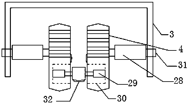
[0014] The offshore cable laying equipment of the present invention includes a strut 1, a shovel handle 2, a wheel frame 3, a digging wheel 4, a second bucket 5, a crawler chassis 6, a chassis 7, a winding drum 8, a first cylinder 9, and a machine base 10. The first support plate 11, the scissor arm 12, the second pin shaft 13, the second hollow 14, the second support plate 15, the first electromagnet 16, the second electromagnet 17, the casing 18, the motor 19, the ring Plate 20, telescopic drill rod 21, cable 22, bearing 23, lug 24, folded tube 25, first pin shaft 26, first hollow 27, second cylinder 28, telescopic shaft 29, groove 30, rotating shaft 31 and the first A bucket 32, a crawler chassis 6 is installed under the chassis 7, a wheel frame 3 is installed on the front side of the crawler chassis 6, a strut 1 is installed between the wheel frame ...


PUM


Abstract

Offshore cable laying equipment, including struts, shovel handles, wheel frames, excavating wheels, second buckets, crawler chassis, chassis, winding drums, first cylinders, machine bases, first support plates, scissor arms, second Second pin, second hollow, second support plate, first electromagnet, second electromagnet, casing, motor, ring plate, telescopic drill rod, cable, bearing, lifting lug, folding tube, first pin, The first hollow, the second cylinder, the telescopic shaft, the groove, the rotating shaft and the first bucket, the crawler chassis is installed under the casing, the wheel frame is installed on the front side of the crawler chassis, and the strut is installed between the wheel frame and the casing; the present invention The advantage is that the first end of the cable can be fixed.

Description

technical field [0001] The invention relates to offshore cable laying equipment and belongs to the technical field of cable laying equipment. Background technique [0002] Offshore cable laying equipment is a special equipment for laying cables on the seabed and underwater, and can also be used as cable maintenance equipment. The cable laying equipment in the prior art does not have the function of fixing the head end of the laid cable, so that the cable is pulled during the cable laying process because the head end of the cable is not fixed, and the cable is easily curled. In order to solve the above difficulties, it is necessary to develop an offshore cable laying device with the function of fixing the cable head. Contents of the invention [0003] The object of the present invention is to provide offshore cable laying equipment. [0004] The problem to be solved by the present invention is that none of the cable laying equipment in the prior art has the function of fi...

Claims


Application Information

Patent Timeline
IPC IPC(8): H02G1/10
CPCH02G1/10
Inventor 赵晓栋皮永蕊刘杰杨婕
Owner YANTAI UNIV
Why Eureka
Try Eureka