Pulse diagnosis instrument based on piezoresistive sensor array
A technology of sensor array and pressure sensor, which is applied in the direction of sensor, diagnosis, and diagnostic signal processing, etc., to achieve the effect of convenient function expansion and suppression of interference
- Summary
- Abstract
- Description
- Claims
- Application Information
AI Technical Summary
Problems solved by technology
Method used
Image

Examples
Embodiment 1
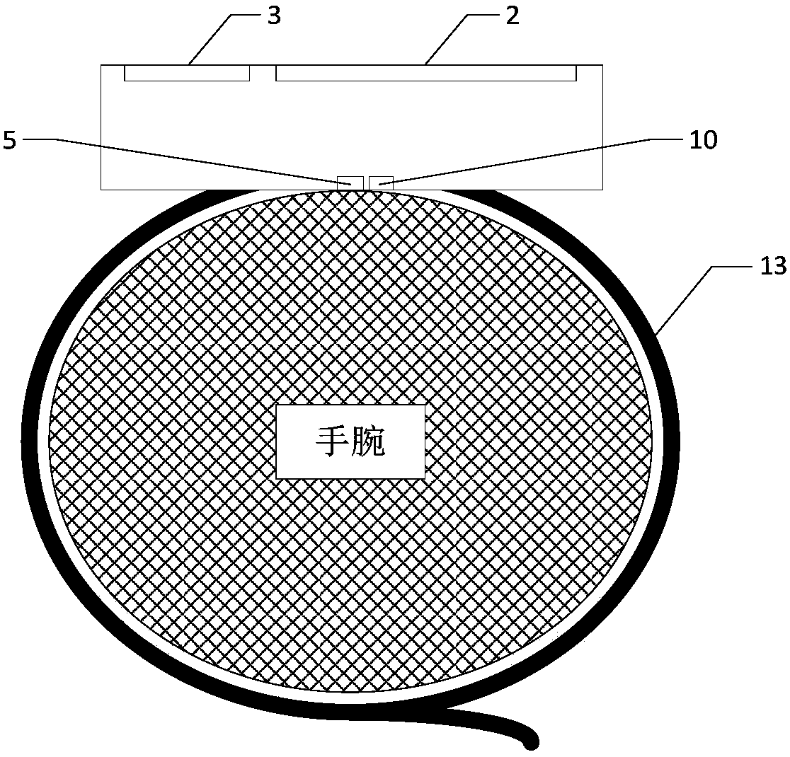
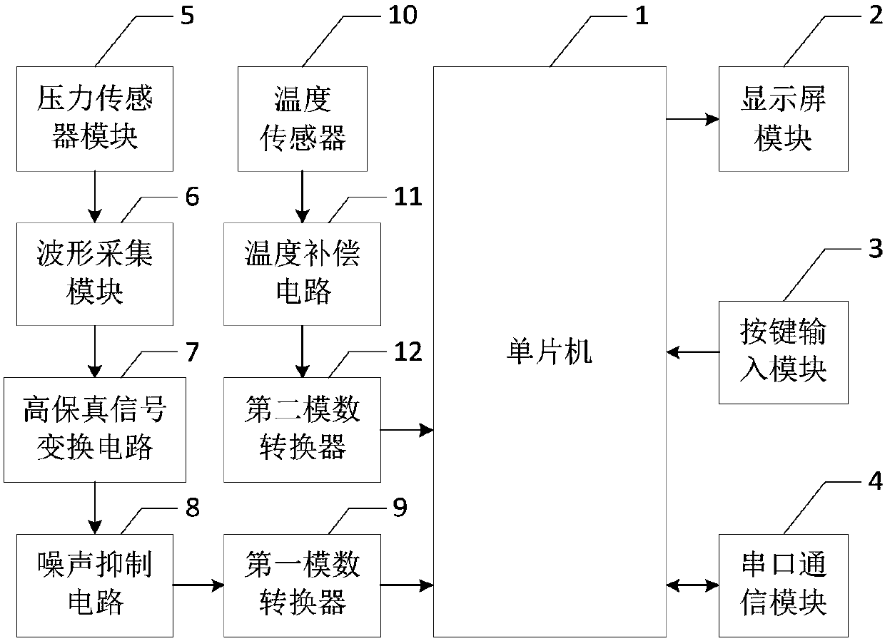
[0030] Embodiment 1 Overall structure of the present invention
[0031] The physical structure of the present invention is as figure 1 shown, the electrical connections are as figure 2As shown, the structure of the present invention includes a single-chip microcomputer 1, a display screen module 2, a key input module 3, a serial port communication module 4, a pressure sensor module 5, a waveform acquisition module 6, a high-fidelity signal conversion circuit 7, a noise suppression circuit 8, a first An analog-to-digital converter 9 , a temperature sensor 10 , a temperature compensation circuit 11 , a second analog-to-digital converter 12 , and a wristband 13 .
Embodiment 2
[0032] Embodiment 2 High-fidelity signal conversion circuit of the present invention
[0033] Such as Figure 4 As shown, the present invention adopts a high-fidelity signal conversion circuit after the waveform acquisition circuit, and the specific structure is that the inverting input terminal of the operational amplifier U1A is used as the input terminal of the high-fidelity signal conversion circuit 7, which is denoted as a port PSensor, connected to the waveform acquisition The common terminal of the eight-choice analog switch chip in module 6, the inverting input terminal and the output terminal of the operational amplifier U1A are connected to the resistor R1, the output terminal is connected to the non-inverting input terminal of the operational amplifier U1B, and the inverting input terminal and output terminal of the operational amplifier U1B The resistance R2 is connected between the terminals, and the output terminal is used as the output terminal of the high-fidel...
Embodiment 3
[0035] Embodiment 3 Noise suppression circuit of the present invention
[0036] Such as Figure 5 As shown, the present invention also adds a noise suppression circuit before the analog-to-digital conversion. The specific structure is that the inverting input terminal of the operational amplifier U2B is connected to the output terminal, and the non-inverting input terminal is connected to one end of the resistor R8 and one end of the capacitor C1, and the capacitor The other end of C1 is grounded, the other end of resistor R8 is connected to one end of resistor R7 and one end of capacitor C2, and the other end of resistor R7 is used as the input end of noise suppression circuit 8, denoted as port RudePI, connected to the output of high-fidelity signal conversion circuit 7 end, the other end of capacitor C2 is connected to the output end of op amp U2B, the output end of op amp U2B is connected to one end of resistor R9, the other end of resistor R9 is connected to one end of ca...
PUM
 Abstract
Description
Claims
Application Information
 - R&D
- Intellectual Property
- Life Sciences
- Materials
- Tech Scout
- Unparalleled Data Quality
- Higher Quality Content
- 60% Fewer Hallucinations
Browse by: Latest US Patents, China's latest patents, Technical Efficacy Thesaurus, Application Domain, Technology Topic, Popular Technical Reports.
© 2025 PatSnap. All rights reserved.Legal|Privacy policy|Modern Slavery Act Transparency Statement|Sitemap|About US| Contact US: help@patsnap.com