Skin stapler nail cartridge connecting structure

A technology of connecting structure and suturing device, which is applied in the direction of surgical fixation nails, etc., can solve the problems of short time, long suture time, and the depth of suture cannot be completely consistent, and achieves the effect of reducing quantity and cost investment.

Inactive Publication Date: 2018-03-16
GUANGZHOU KEHUIZE BIOTECH CO LTD
View PDF0 Cites 2 Cited by
  • Summary
  • Abstract
  • Description
  • Claims
  • Application Information

AI Technical Summary

Problems solved by technology

[0002] In human surgery, various kinds of sutures are used to suture the skin wounds by hand. This traditional suture method not only takes a long time to suture, but also because the suture depth depends on the manual operation of the operator, the suture depth on both sides of the wound is often not completely consistent, resulting in There is a slight deviation in the alignment of the cortex, which leads to relatively wide and unsightly scars after wound healing. Therefore, a skin stapler that uses metal staples to staple epidermal wounds was invented by referring to the stapler principle. This skin stapler is mechanically operated manually. Staple the superficial wound, the staples have the same depth, the left and right skin edges are accurate to the skin, the scar is small and beautiful after the wound heals, and the whole suturing process takes a short time, and the metal staples can be used after the postoperative wound heals. The staple removal tool is easy to remove the staples, which is favored by the majority of surgeons

Method used


Image

  • Skin stapler nail cartridge connecting structure
  • Skin stapler nail cartridge connecting structure
  • Skin stapler nail cartridge connecting structure

Examples


Embodiment Construction

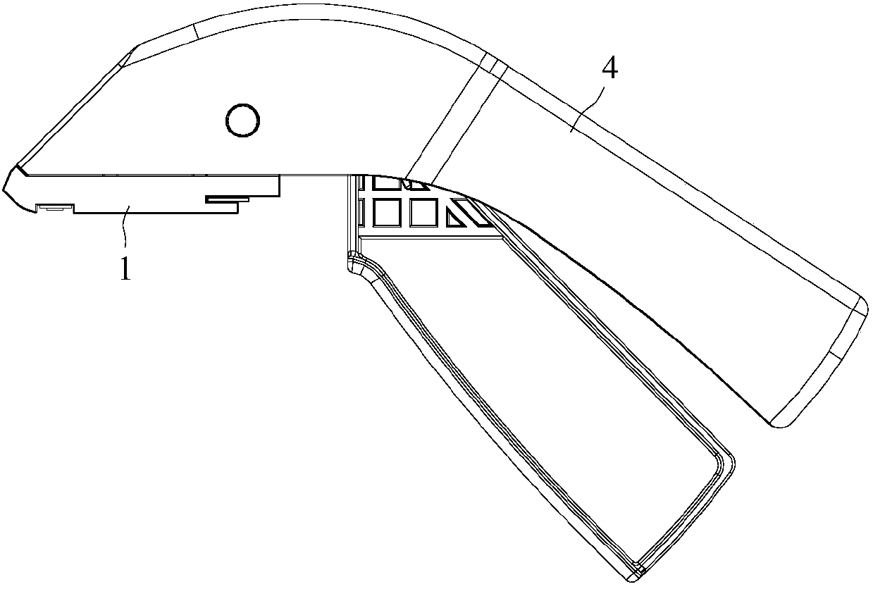
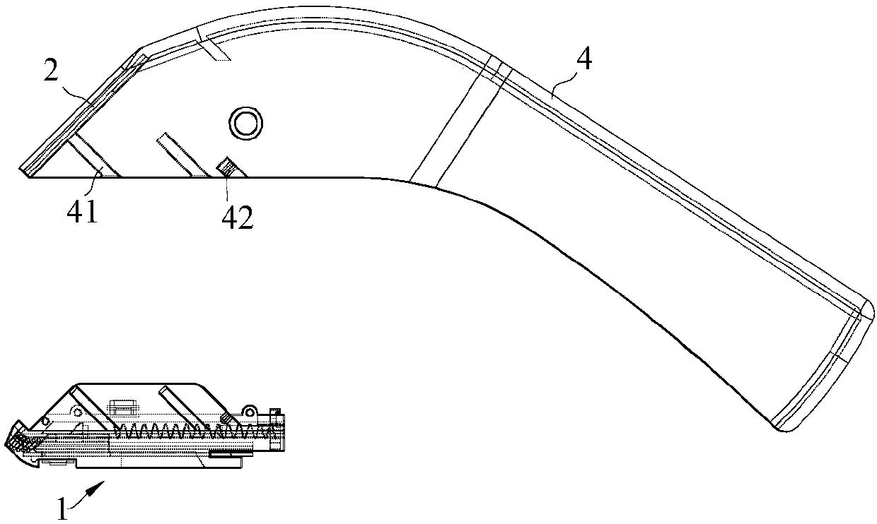
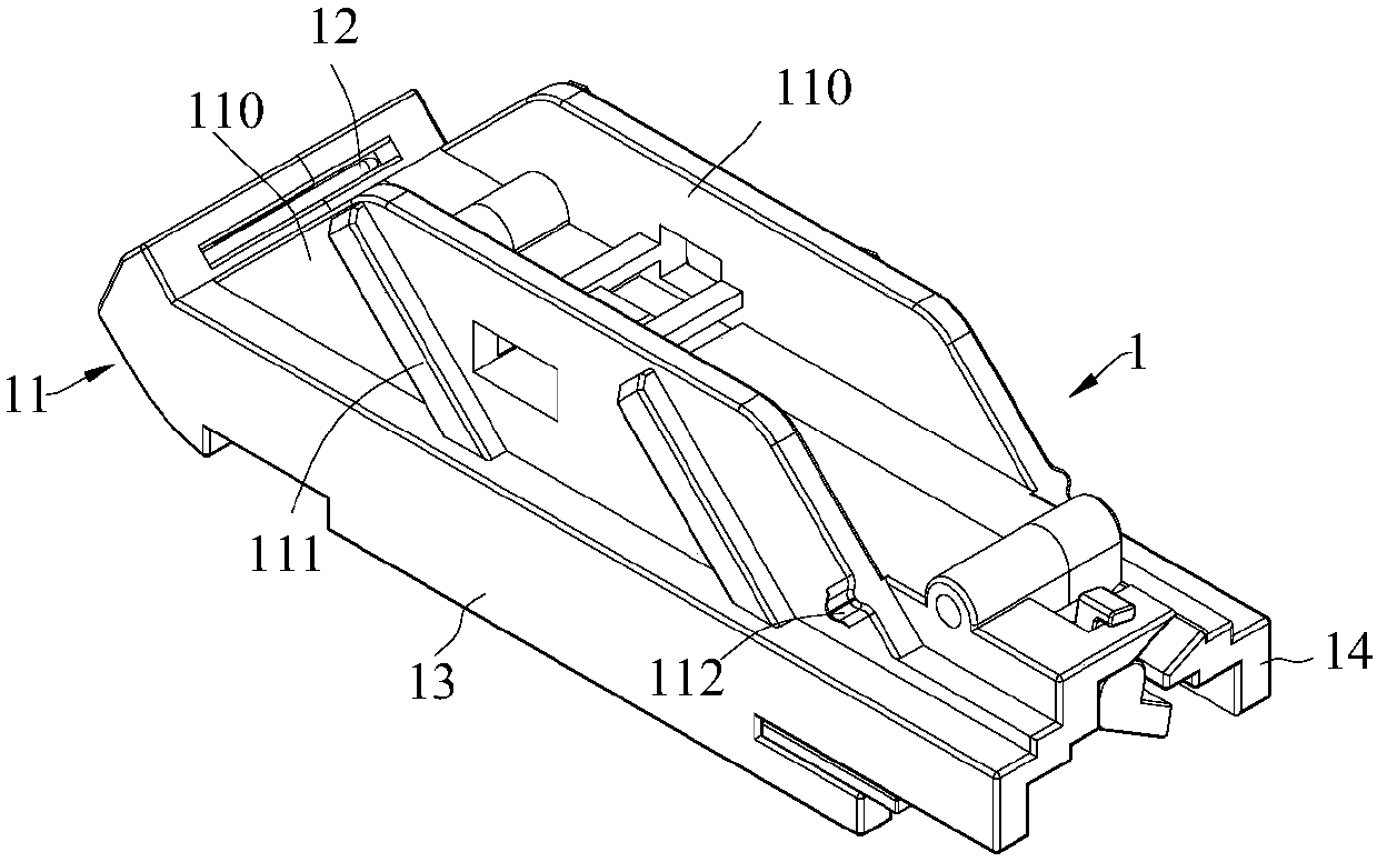
[0021] refer to Figure 1 to Figure 7 , which shows the specific structure of the preferred embodiment of the present invention. The structural features of each part of the present invention will be described in detail below, and if there is a description to the direction (up, down, left, right, front and back), it is based on figure 2 , image 3 , the structure shown is a reference description, but the actual application direction of the present invention is not limited thereto.

[0022] The present invention provides a staple cartridge connection structure for a skin stapler, comprising a matrix 4 and a staple cartridge 1, the staple cartridge 1 is mounted on the matrix 4 through a quick release structure, and the staple cartridge 1 is provided with an upward protruding The positioning connection part 110 of the mother body, the quick release structure includes the guide protrusion 111 and the card protrusion 112 provided on the positioning connection part 110 of the moth...


PUM


Abstract

The invention discloses a nail cartridge connection structure for a skin suturing device, which is used in the technical field of surgical instruments and includes a mother body and a nail cartridge. The nail cartridge is installed on the mother body through a quick-release structure. The structure includes guide protrusions and card protrusions on the positioning connection part of the mother body and guide grooves and card slots on the mother body. There is a nail storage bin inside the nail bin, and the nail outlet is provided at the front end of the nail storage bin. , the nail magazine is provided with a nail presser plate passing groove above the nail outlet, and the front end of the positioning connection part of the mother body is provided with a nail presser plate guide surface that can guide the nail presser plate into the nail presser plate passage groove. The mother body and the staple cartridge adopt a detachable split structure design. The staple cartridge can be designed for one-time use, and the mother body is designed to be reusable. The mother body can be used repeatedly after cleaning and sterilization, which not only reduces the cost input of the skin stapler , but also reduce the amount of medical waste. At the same time, it can ensure that the nail plate can be smoothly guided to protrude after the connection, so as to realize the nail pushing.

Description

technical field [0001] The invention is used in the technical field of surgical instruments, and in particular relates to a nail cartridge connecting structure of a skin stapler. Background technique [0002] In human surgery, various kinds of sutures are used to suture the skin wounds by hand. This traditional suture method not only takes a long time to suture, but also because the suture depth depends on the manual operation of the operator, the suture depth on both sides of the wound is often not completely consistent, resulting in There is a slight deviation in the alignment of the cortex, which leads to relatively wide and unsightly scars after wound healing. Therefore, a skin stapler that uses metal staples to staple epidermal wounds was invented by referring to the stapler principle. This skin stapler is mechanically operated manually. Staple the superficial wound, the staples have the same depth, the left and right skin edges are accurate to the skin, the scar is sma...

Claims


Application Information

Patent Timeline
IPC IPC(8): A61B17/072
CPCA61B17/072A61B17/0682A61B2017/07271
Inventor 岑道卷李桂存
Owner GUANGZHOU KEHUIZE BIOTECH CO LTD
Why Eureka
Try Eureka