Slurry processing stirring tank

A mixing tank and slurry technology, applied to mixer accessories, mixers with rotating stirring devices, chemical/physical processes, etc., can solve problems such as difficulties, slurry mixing, and consumption of driving force, and achieve reasonable structural design and sufficient mixing effect , to ensure the sealing effect

Inactive Publication Date: 2018-03-16
陈钰杰
View PDF0 Cites 2 Cited by
  • Summary
  • Abstract
  • Description
  • Claims
  • Application Information

AI Technical Summary

Problems solved by technology

Traditional methods include mechanical stirring and aeration stirring. Since the concentration of the slurry is higher than that of the liquid, it is difficult for a single-axis stirring rod to fully stir the slurry in the entire tank, and the stirring effect is poor; at the same time, aeration and stirring It will also be more difficult due to the high concentration of the slurry, and it will consume a lot of driving force, and the structural design is very unreasonable

Method used


Image

  • Slurry processing stirring tank
  • Slurry processing stirring tank
  • Slurry processing stirring tank

Examples


Embodiment Construction

[0016] The following will clearly and completely describe the technical solutions in the embodiments of the present invention with reference to the accompanying drawings in the embodiments of the present invention. Obviously, the described embodiments are only some, not all, embodiments of the present invention. Based on the embodiments of the present invention, all other embodiments obtained by persons of ordinary skill in the art without making creative efforts belong to the protection scope of the present invention.

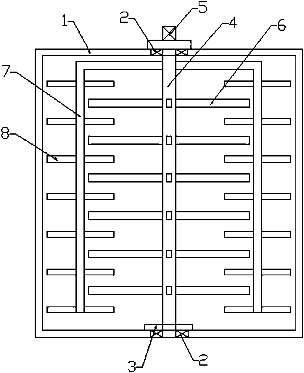
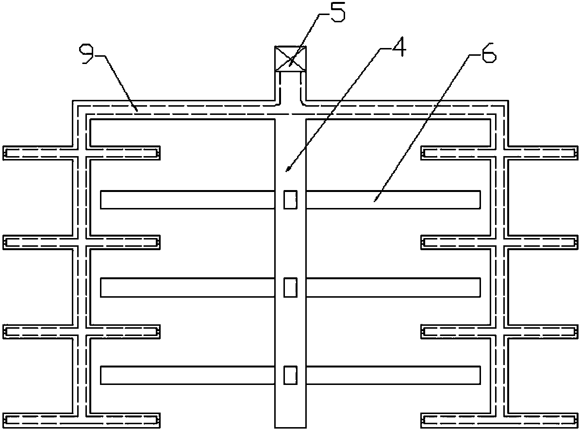
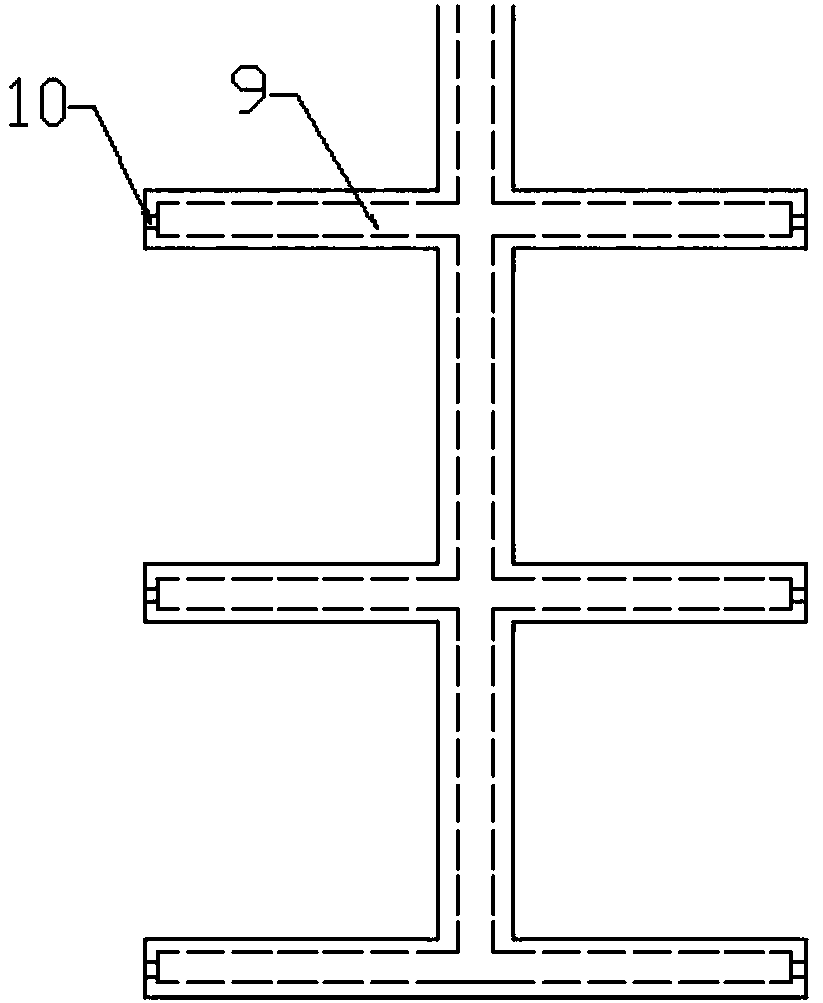
[0017] see Figure 1-3 , the present invention provides a technical solution: a stirring tank for slurry treatment, including a tank 1 and a stirring device arranged in the tank 1; The stirring blade A6 arranged on the rotating shaft 4, the pair of stirring side rods 7 connected to the rotating shaft 4 and the stirring blades B8 evenly arranged on the stirring side rod 7; The upper bearing 2 is connected to the box body 1, and there is a sealing ring 3 at the...


PUM


Abstract

The invention discloses a slurry processing stirring tank. The slurry processing stirring tank comprises a tank body and a stirring device arranged in the tank body; the stirring device comprises a rotating shaft arranged in the tank body along a vertical direction, stirring blades A uniformly arranged on the rotating shaft, a pair of stirring side rods connected with the rotating shaft, and stirring blades B uniformly arranged on the stirring side rod; a communicated liquid-guiding groove is arranged in the rotating shaft, the stirring side rod and the stirring blades B, the liquid-guiding groove is extended to each stirring blade B through the stirring side rod by an upper end of the rotating shaft, and an end part of the stirring blade B comprises a thin liquid outlet communicated withthe liquid-guiding groove; several stirring blades A and the stirring blades B are arranged in the tank body from center to outside, the stirring effect is complete, moisture is added in the slurry with large concentration regularly, drying of the slurry is prevented, water is added at each part in the device thorough the liquid-guiding groove and the thin liquid outlet, the slurry and water are uniformly mixed in a short time, and the design of an integral structure is reasonable.

Description

technical field [0001] The invention relates to the technical field of chemical equipment, in particular to a mixing tank for slurry treatment. Background technique [0002] The solid-liquid mixed slurry system is widely used in my country, such as coal water slurry, limestone slurry in wet flue gas desulfurization system, etc. In order to keep the slurry properties uniform and prevent the slurry system from settling, it is necessary to keep the slurry tank for storing slurry. Stir. Traditional methods include mechanical stirring and aeration stirring. Since the concentration of the slurry is higher than that of the liquid, it is difficult for a single-axis stirring rod to fully stir the slurry in the entire tank, and the stirring effect is poor; at the same time, aeration and stirring It will also be more difficult due to the large concentration of the slurry, and will consume a large amount of driving force, and the structural design is very unreasonable. Contents of the...

Claims


Application Information

Patent Timeline
Patent Type & Authority Applications(China)
IPC IPC(8): B01F7/18B01F15/00
CPCB01F27/074B01F27/191B01F27/90B01F35/00B01F2035/351
Inventor 陈钰杰
Owner 陈钰杰
Why Eureka
Try Eureka