A wind power blade flash cutting device

A cutting device and wind power blade technology, applied in textiles and papermaking, cutting of textile materials, metal processing, etc., can solve the problems of inaccurate control, low cutting efficiency, time-consuming and laborious, etc., and achieve ingenious design and clamping. Tight, flexible effects

Active Publication Date: 2019-12-20
上海玻璃钢研究院东台有限公司
View PDF6 Cites 0 Cited by
  • Summary
  • Abstract
  • Description
  • Claims
  • Application Information

AI Technical Summary

Problems solved by technology

[0002] At present, wind power blades are formed by bonding the upper blade and the lower blade in molds. There will be redundant glass fiber cloth at the joint between the upper mold and the lower mold, and multiple glass fiber cloths are required for cutting. In the prior art, the Usually, the operator holds the cutting tool and then cuts at the position to be cut. However, the accuracy of the cutting operation is controlled by the operator and is not under precise control at all. In addition, manual cutting is inefficient, time-consuming and laborious. High difficulty

Method used


Image

  • A wind power blade flash cutting device
  • A wind power blade flash cutting device
  • A wind power blade flash cutting device

Examples


Embodiment Construction

[0021] The content of the present invention will be further described in detail below in conjunction with the accompanying drawings.

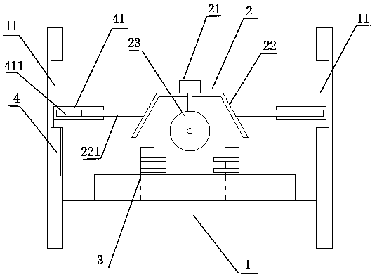
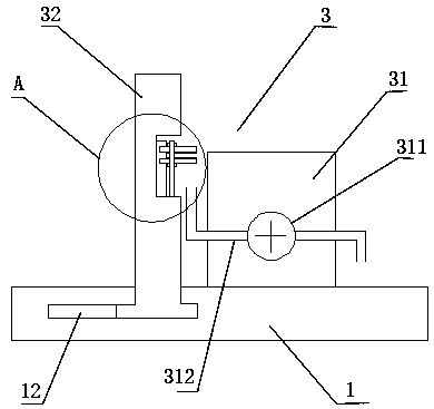
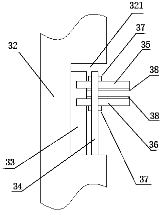
[0022] like figure 1 As shown, a wind power blade flash cutting device includes a U-shaped bracket 1 , a cutting mechanism 2 , a clamping mechanism 3 , and a telescopic device 4 . The clamping mechanism 3 is installed on the bottom of the U-shaped bracket 1, and the clamping mechanism 3 is used for clamping flash. The cutting mechanism 2 is installed above the clamping mechanism 3 . The cutting mechanism 2 includes a dust shield 22 , a driving motor 21 , and a cutting disc 23 . The cutting disk 23 is installed in the dustproof cover 22, which can effectively prevent the flying phenomenon of glue dust produced during cutting. The driving motor 21 is installed on the upper end of the dust shield 22, and the driving motor 21 drives the cutting disk 23 to rotate. Two mounting grooves 11 are respectively provided on the insides of the two sides ...


PUM


Abstract

The invention discloses a wind turbine blade flash cutting device. The wind turbine blade flash cutting device comprises a U-shaped bracket, a cutting mechanism, a clamping mechanism and telescopic devices. The clamping mechanism is installed at the bottom of the U-shaped bracket. The cutting mechanism is mounted above the clamping mechanism and comprises a dust screen cover, a driving motor and acutting disc. The cutting disc is installed in the dust screen cover. The driving motor is installed at the upper end of the dust screen cover. The driving motor drives the cutting disc to rotate. Mounting grooves are formed in the inner sides of the two edges of the U-shaped bracket correspondingly. The telescopic devices are arranged in the mounting grooves. Connecting rods are arranged on thetwo sides of the dust screen cover. The upper ends of the telescopic devices are fixed to the connecting rods on the two sides of the dust screen cover. The wind turbine blade flash cutting device isprecise in cutting and high in cutting efficiency.

Description

technical field [0001] The invention relates to a wind power blade flash cutting device. Background technique [0002] At present, wind power blades are formed by bonding the upper blade and the lower blade in molds. There will be redundant glass fiber cloth at the joint between the upper mold and the lower mold, and multiple glass fiber cloths are required for cutting. In the prior art, the Usually, the operator holds the cutting tool and then cuts at the position to be cut. However, the accuracy of the cutting operation is controlled by the operator and is not under precise control at all. In addition, manual cutting is inefficient, time-consuming and laborious. High difficulty. Contents of the invention [0003] In view of the shortcomings of the above-mentioned prior art, the problem to be solved by the present invention is: to provide a wind power blade flash cutting device with precise cutting and high cutting efficiency. [0004] In order to solve the above proble...

Claims


Application Information

Patent Timeline
Patent Type & Authority Patents(China)
IPC IPC(8): B29C37/02B26D1/15B26D7/04B26D7/18B26D7/22D06H7/00
CPCB26D1/151B26D7/04B26D7/1863B26D7/22D06H7/00
Inventor 吉玉峰夏保付韩飞张文艳张永金
Owner 上海玻璃钢研究院东台有限公司
Why Eureka
Try Eureka