
Mold compounding system adapting to pipe pile molds of multiple specifications

A pipe pile mold, multi-specification technology, applied in the direction of molds, etc., can solve the problems of inability to tighten bolts, stuck, speed errors, etc., and achieve the effect of continuous and uninterrupted production, ensuring accuracy, and ensuring detection accuracy.

Active Publication Date: 2018-03-16
HUBEI UNIV OF TECH
View PDF8 Cites 9 Cited by
  • Summary
  • Abstract
  • Description
  • Claims
  • Application Information

AI Technical Summary

Problems solved by technology

The ferrule catches the bolt to complete the upturning action. This action is completed when the whole mechanism and the pipe pile formwork move synchronously. Due to the speed error, there is an error in the axial displacement. Every 2m running produces a ±25mm distance error, and there is an upturning During the process, there is a possibility of jamming due to large position errors, and the solution is to turn up the bolts one by one, which is inefficient
In this technical solution, the automatic jackhammer device has only one set of jackhammers on one side. In actual production, the jackhammer device needs to return to the initial position after each set of bolts is tightened, and waits for the next set of bolts. Due to the time difference of the initial position, the wind gun device cannot tighten the bolts with a short distance, so this scheme is not suitable for the pipe pile formwork with a short distance between the bolts

Method used


Image

  • Mold compounding system adapting to pipe pile molds of multiple specifications
  • Mold compounding system adapting to pipe pile molds of multiple specifications
  • Mold compounding system adapting to pipe pile molds of multiple specifications

Examples


Embodiment Construction

[0041] The present invention is illustrated below in conjunction with accompanying drawing

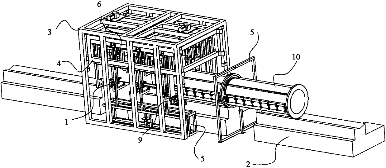
[0042] Such as Figure 1 to Figure 13 As shown, a pipe pile mold clamping system adapting to multiple specifications, including pipe pile mold conveying device 2, outer frame 3, inner frame 4, detection device 5, jackhammer device 6, jackhammer installation rod 7, bolt supporting guide rail 8. Bolt leveling mechanism 9 and bolt righting and positioning mechanism 1,

[0043] The pipe pile mold conveying device 2 is used to convey the pipe pile mold 10 along its axial direction at a constant speed;

[0044] Described outer frame 3 is arranged on the top of pipe pile mold conveying device 2, is used as the support of whole device;

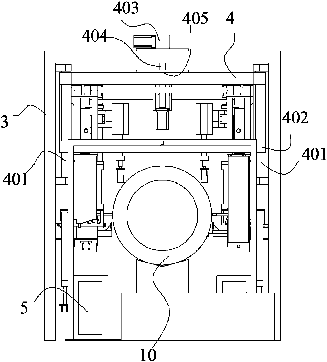
[0045] Such as figure 2 , Figure 12 and 13 As shown, the inner frame 4 is installed inside the outer frame 3 through a lifting mechanism. Specifically, four inner frame guide rods 401 are arranged on the support rods around the outer frame 3, and four i...


PUM


Abstract

The invention discloses a mold compounding system adapting to pipe pile molds of multiple specifications. The mold compounding system comprises a pipe pile mold conveying device, an outer frame, an inner frame, a detecting device, bolt supporting guide rails, jackhammer devices, bolt leveling mechanisms and bolt straightening and locating mechanisms, wherein the jackhammer devices, the bolt leveling mechanisms and the bolt straightening and locating mechanisms are mounted on jackhammer mounting rods. The pipe diameters of the pipe pile molds are detected through the detecting device, then theheight of the inner frame and the height of the detecting device are adjusted through lifting mechanisms, the distance of the two jackhammer mounting rods is adjusted through a translation mechanism to adapt to the pipe diameters of the pipe pile molds, then bolts are leveled through four-connecting-rod mechanisms with electromagnets, the horizontal bolts are placed on the bolt supporting guide rails to advance, then the bolts are turned over through the four-connecting-rod mechanisms of the bolt straightening and locating mechanisms and pushed to groove openings to be located through telescopic push rods, and finally the jackhammer devices move downwards to complete tightening work. The mold compounding system can achieve automatic detecting and adapt to mold compounding of the pipe pilemolds different in pipe diameter, pipe length and bolt distance specification, during mold compounding, bolt tightening is accurate, and efficiency is high.

Description

technical field [0001] The invention belongs to the field of prestressed concrete pipe pile production and processing production lines, and relates to a pipe pile mold clamping device, in particular to a pipe pile mold clamping system adaptable to multiple specifications. Background technique [0002] In the field of prestressed concrete pipe pile production, due to its high labor intensity, intensive labor demand, and harsh production environment, the demand for automated production is even stronger. The steel molds used for the production of pipe piles are divided into an upper mold and a lower mold, which are fixed by bolt tightening. Before the bolts are tightened, the bolts need to be turned over and straightened. Tightening requires a lot of manpower, low efficiency, and has not been fully automated. The main reasons are as follows: 1. Most of the production equipment for prestressed concrete pipe piles is of the extensive type, but the righting and tightening of bolts...

Claims


Application Information

Patent Timeline
IPC IPC(8): B28B21/82
CPCB28B21/82
Inventor 汤亮龚发云卢文政李建章进何仁杰杜卫东李倩
Owner HUBEI UNIV OF TECH
Learn More