Synchronous feeding structure of lower traction wheel

A tugboat and coaxial technology, which is applied in the field of sewing machines, can solve problems affecting product quality, sewing material movement, sewing material misalignment, etc., and achieve the effect of compact structure, convenient connection and reasonable structural design

Active Publication Date: 2018-03-16
JACK SEWING MASCH CO LTD
View PDF8 Cites 7 Cited by
  • Summary
  • Abstract
  • Description
  • Claims
  • Application Information

AI Technical Summary

Problems solved by technology

[0003] Although the cloth feeding through the rear tugboat has the advantages of simple operation and reliability, but in the sewing operation process, because only the upper tugboat pulls the cloth, the upper and lower sewing materials are often misplaced when sewing multi-layer sewing materials, and the sewing materials are prone to tearing. Tendency phenomenon, affecting product quality

Method used


Image

  • Synchronous feeding structure of lower traction wheel
  • Synchronous feeding structure of lower traction wheel
  • Synchronous feeding structure of lower traction wheel

Examples


Embodiment 1

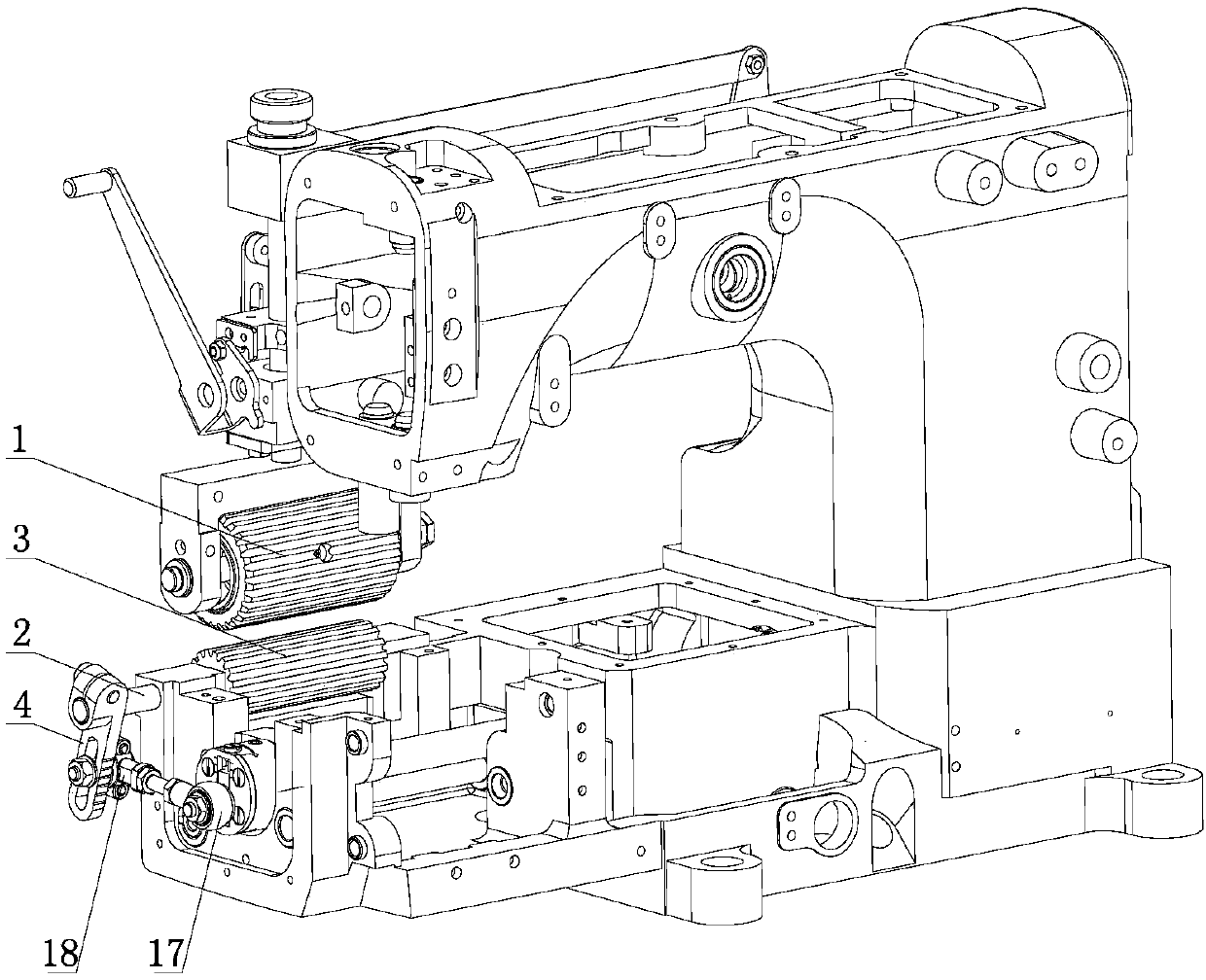
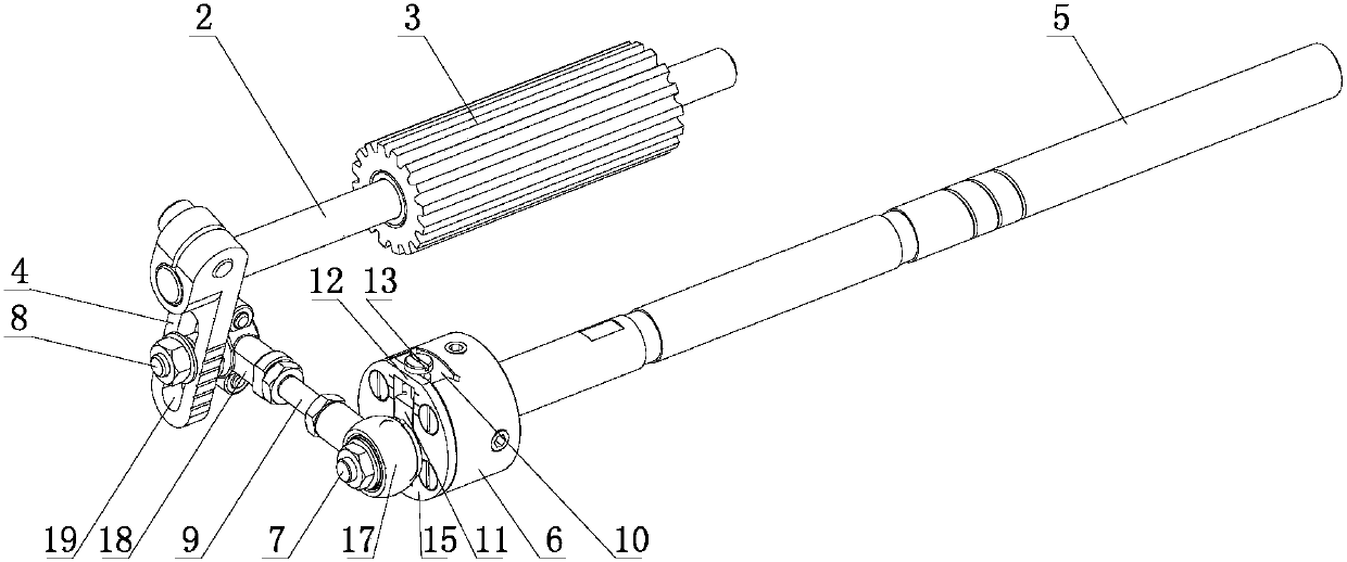
[0029] like figure 1 and figure 2 The synchronous feeding structure of the lower tugboat shown includes a rotating shaft 2 parallel to the upper tugboat 1 and a lower tugboat 3 coaxially sleeved on the rotating shaft 2. The lower tugboat 3 is located directly below the upper tugboat 1. and set opposite to the upper tugboat 1, such as figure 1 As shown, the lower tug wheel 3 is placed horizontally, and its highest point is not lower than the upper surface of the workbench. When feeding is required, the lower tug wheel 3 rotates in one direction under the action of the transmission assembly. like figure 1 and figure 2 As shown, a swing rod 4 is fixed on the rotating shaft 2, and a transmission assembly for driving the swing rod 4 to swing when the spindle 5 rotates is provided between the swing rod 4 and the main shaft 5 of the sewing machine. The one-way assembly used to limit the lower tugboat 3 to rotate in one direction all the time when the fork 4 swings.

[0030] li...

Embodiment 2

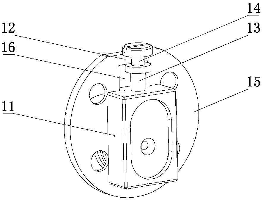
[0040] The structural principle of this embodiment is basically the same as that of Embodiment 1, the difference is that the adjustment limit unit includes a threaded hole arranged in the connecting sleeve 6 and a bolt threaded in the threaded hole, and the threaded hole and the slide The sides of the slot 10 are vertical and the inner end of the threaded hole communicates with the sliding slot 10 , and the inner end of the bolt abuts against the sliding block 10 .


PUM


Abstract

The invention provides a synchronous feeding structure of a lower traction wheel, and belongs to the technical field of sewing machines. The problem that an existing sewing machine only uses upper andrear traction wheels for feeding, and accordingly when multiple layers of sewing materials are conveyed, the upper and lower layers of sewing materials are always staggered. The synchronous feeding structure of the lower traction wheel structurally comprises a rotating shaft and the lower traction wheel, the rotating shaft penetrates through a workbench of the sewing machine and is parallel to the upper traction wheel, the rotating shaft is coaxially sleeved with the lower traction wheel, the lower traction wheel is located under the upper traction wheel and opposite to the upper traction wheel, a swing rod is fixed to the rotating shaft, a transmission assembly used for driving the swing rod to swing when a main shaft rotates is arranged between the swing rod and the main shaft of the sewing machine, and a one-way assembly used for limiting the lower traction wheel to rotate in one direction all the time when the swing rod swings is arranged between the rotating shaft and the lower traction wheel. The synchronous feeding structure has the advantages that the structural design is reasonable, the application range is wide, and the sewing materials are not staggered or wrinkled whenmultiple layers of sewing materials are sewn.

Description

technical field [0001] The invention belongs to the technical field of sewing machines, and relates to a synchronous feeding structure, in particular to a synchronous feeding structure of a lower tug wheel which cooperates with an upper tug wheel. Background technique [0002] The feeding method of the traditional sewing machine is the feeding dog, and partly the needle and the presser foot participate in the feeding together with the feeding dog. This feeding method has limited feeding force, especially for sewing materials with special materials, the feeding is more difficult. Indicates that the stitches are too small. For this reason, Chinese patent discloses a kind of rear tugboat device [application publication number CN106676764A], comprises cloth feeding shaft, and cloth feeding shaft is connected with upper crank by more than one connecting rod by lower crank, and upper crank is fixed on the mop shaft, There is also a fixed frame and an adjusting crank on the mop sh...

Claims


Application Information

Patent Timeline
Patent Type & Authority Applications(China)
IPC IPC(8): D05B27/18D05B69/02
CPCD05B27/18D05B69/02
Inventor 包彦烘杨聪聪王志李卫超
Owner JACK SEWING MASCH CO LTD
Why Eureka
Try Eureka