
Method of testing dielectric dissipation factor and capacitance without removing high-voltage leads of transformer

A technology of dielectric loss factor and high-voltage leads, which is applied in the direction of capacitance measurement, measuring device, and measurement of electrical variables, etc. It can solve the problems of the influence of test data, the difficulty of unplugging the power transformer of ultra-high voltage lines, and the difficulty of whether the transformer is normal or not. , to achieve the effect of shortening the interval time, enhancing system reliability and reducing downtime

Active Publication Date: 2020-02-14
STATE GRID FUJIAN ELECTRIC POWER CO LTD +2
View PDF2 Cites 0 Cited by
  • Summary
  • Abstract
  • Description
  • Claims
  • Application Information

AI Technical Summary

Problems solved by technology

[0021] According to the conventional non-disconnection test method disclosed in CN101354418 B, it is difficult to carry out the non-disconnection test of 500Kv and above ultra-high voltage line power transformers
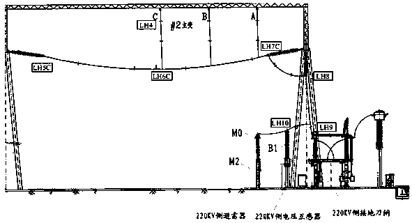
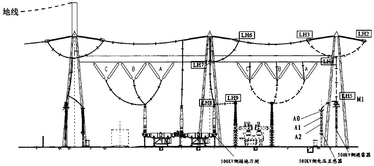
[0022] Judging from the above situation, Option 1 is the most accurate test for testing the transformer, but because the wires on the three sides are connected, the wires are basically connected to the lightning arrester, capacitive voltage transformer, wire, insulator string, and wire support. Auxiliary equipment such as insulators (hereinafter referred to as auxiliary capacitance value), these ancillary equipment have a great impact on the test data when using conventional methods for testing, and cause great difficulty in judging whether the transformer is normal or not.

Method used


Image

  • Method of testing dielectric dissipation factor and capacitance without removing high-voltage leads of transformer
  • Method of testing dielectric dissipation factor and capacitance without removing high-voltage leads of transformer
  • Method of testing dielectric dissipation factor and capacitance without removing high-voltage leads of transformer

Examples


Embodiment Construction

[0060] The present invention will be further described below in conjunction with the accompanying drawings and specific embodiments.

[0061] In order to obtain more accurate data, the neutral point connection line of the transformer was removed on site, and the remaining high-voltage side lead wires and medium-voltage side lead wires did not need to be removed because of their high heights.

[0062] In this embodiment, the three-phase 500Kv autotransformer is taken as an example. Only the neutral point lead wire needs to be removed. Because there are many live parts involved in the test and the safety risk is high, this embodiment considers removing the low-voltage winding lead wire, and at the same time, accurate Data and easy security management and control.

[0063] Such as Figure 1-3 As shown, a method for testing the dielectric loss factor and capacitance of a transformer in this embodiment without removing the high-voltage lead wires includes the following steps:

[...


PUM


Abstract

The invention relates to a method for testing a dielectric loss factor and electric capacity without dismounting a high-voltage lead of a transformer. After connection of wires at three sides of a transformer, the wires are connected to accessory equipment like a lightning arrester, a capacitive voltage transformer, an insulator string, and supporting insulators of the leads. According to the invention, attached capacitance values and dielectric loss values brought by the accessory equipment are measured separately; when no lead is dismounted, the tested data are calculated and transformed into real data of the transformer; the converted data are compared with original data to determine whether the transformer is in a normal state. Because the testing is carried out while no lead is dismounted, the risk of operation is reduced; and the induced electricity is controlled in advance.

Description

technical field [0001] The invention relates to a method for testing dielectric loss factor and capacitance of a transformer without removing high-voltage lead wires. Background technique [0002] Because after the wires on the three sides are connected, the wires are basically connected to auxiliary equipment such as lightning arresters, capacitive voltage transformers, insulator strings, and supporting insulators for wires (hereinafter referred to as auxiliary capacitance values), and these auxiliary equipment will be connected to the transformer through wires. As a result, it has a great impact on the test data. [0003] Solution 1: The current routine test method commonly used for transformers is to remove the connections on each side of the transformer, and then perform routine measurements on various data of the transformer. For details, refer to the enterprise standard of the State Grid Corporation of China, Q / GDW1168-2013, transmission and transformation Electrical ...

Claims


Application Information

Patent Timeline
Patent Type & Authority Patents(China)
IPC IPC(8): G01R27/26
CPCG01R27/2605G01R27/2694
Inventor 徐育福林滔林瀚伟孙亚辉黄金魁刘旭吴方连陈闽江
Owner STATE GRID FUJIAN ELECTRIC POWER CO LTD
Learn More