Display panel and display device

A technology of display panel and register bank, applied in static indicators, instruments, etc., can solve the problem of increased power consumption, and achieve the effect of reducing power consumption

Inactive Publication Date: 2018-03-16
WUHAN TIANMA MICRO ELECTRONICS CO LTD
View PDF8 Cites 33 Cited by
  • Summary
  • Abstract
  • Description
  • Claims
  • Application Information

AI Technical Summary

Problems solved by technology

However, when the display panel only needs to display part of the content such as time, calendar, weather, etc., the gate drive circuit needs to scan each

Method used


Image

  • Display panel and display device
  • Display panel and display device
  • Display panel and display device

Examples


Embodiment 1

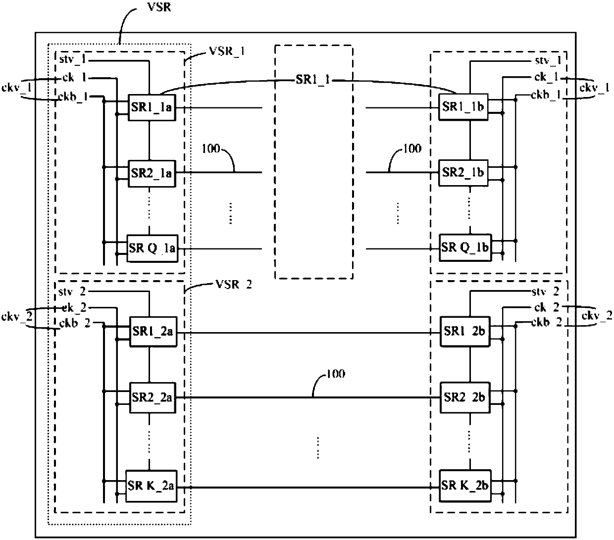
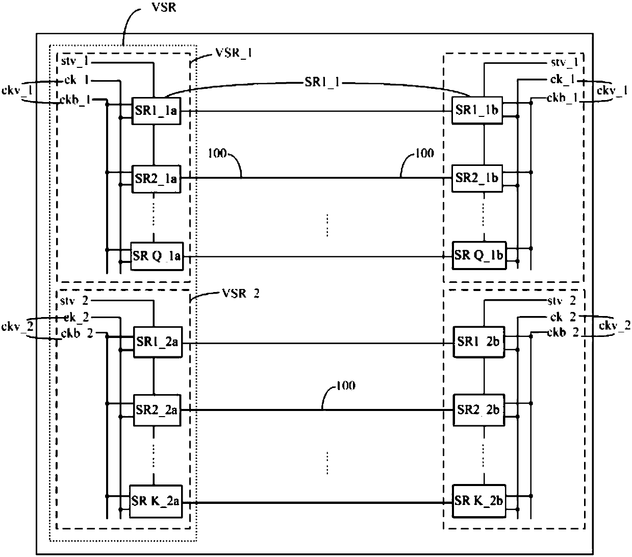
[0047] Taking M=2 as an example, the display panel is generally provided with pixels for display, and the driving signal line extends along the row direction of the pixels. In specific implementation, in the display panel provided by the embodiment of the present invention, such as Figure 7 As shown, the display panel can be divided into two areas, namely: a first area aa_1 and a second area aa_2. The first register group VSR_1 of the two register groups is used to drive the driving signal line 100 in the first area aa_1, so that the driving signal line 100 in the first area aa_1 can be driven. The second register group VSR_2 is used to drive the driving signal line 100 in the second area aa_2, so that the driving signal line 100 in the second area aa_2 can be driven.

[0048] Generally, the display panel can adopt a double-sided driving method to realize the driving function. In specific implementation, in the display panel provided by the embodiment of the present invention, e...

Embodiment 2

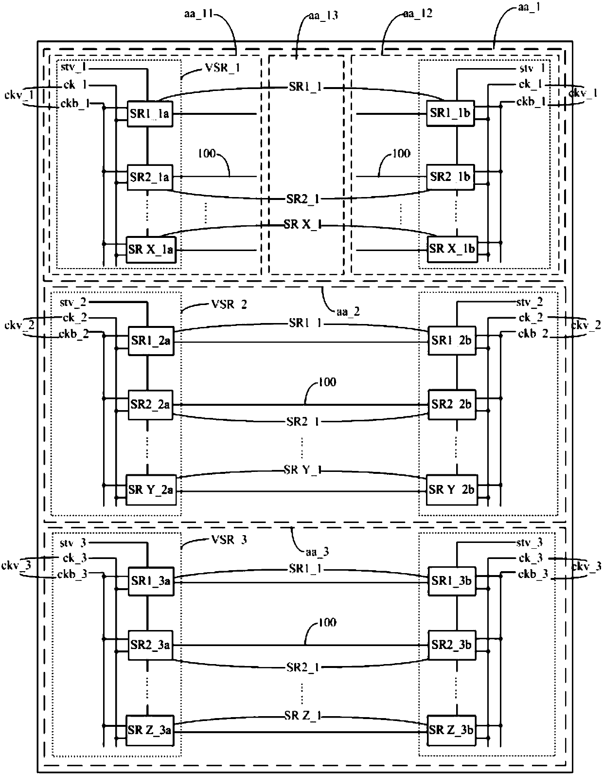
[0057] Taking M=3 as an example, in specific implementation, in the display panel provided by the embodiment of the present invention, such as image 3 As shown, the display panel can be divided into three areas, namely: a first area aa_1, a second area aa_2, and a third area A_3. The first register group VSR_1 of the three register groups is used to drive the driving signal line 100 in the first area aa_1, so that the driving signal line 100 in the first area aa_1 can be driven. The second register group VSR_2 is used to drive the driving signal line 100 in the second area aa_2, so that the driving signal line 100 in the second area aa_2 can be driven. The third register group VSR_3 is used to drive the driving signal line 100 in the third area A_3, so that the driving signal line 100 in the third area A_3 can be driven.

[0058] Generally, the display panel can adopt a double-sided driving method to realize the driving function. In specific implementation, in the display panel ...


PUM


Abstract

The invention discloses a display panel and a display device. The shift registers in a drive control circuit are grouped, the registers in each register group are cascaded, and each register group iselectrically connected with a plurality of adjacent drive signal lines. Different frame start signal terminals and different clock control signal terminals are set for the register groups so that eachregister group can drive the drive signal lines electrically connected therewith under independent control. During the regional display process of the display panel, part of the register groups are made to work independently so that the display in the regions corresponding to the working registers is driven and the display in the regions corresponding to the remaining register groups is not driven, thus reducing the power consumption. During overall display of the display panel, the register groups work in order, line-by-line display driving is carried out on the drive signal lines in the display panel, and therefore, the display panel achieves an overall display function.

Description

Technical field [0001] The present invention relates to the field of display technology, in particular to a display panel and a display device. Background technique [0002] With the rapid development of display technology, display panels are increasingly developing towards high integration and low cost. Among them, the array substrate row drive (Gate Driver on Array, GOA) technology integrates the thin film transistor (Thin Film Transistor, TFT) gate switch circuit on the array substrate of the display panel to form a scan drive for the display panel, so that the gate can be omitted. The bonding (Bonding) area and fan-out (Fan-out) area of ​​the integrated circuit (Integrated Circuit, IC) can not only reduce the product cost in terms of material cost and manufacturing process, but also enable the display panel to achieve Beautiful design with symmetrical sides and narrow border. [0003] At present, the general gate drive circuit is composed of multiple cascaded shift registers....

Claims


Application Information

Patent Timeline
IPC IPC(8): G09G3/36G09G3/3266
CPCG09G3/3266G09G3/3674G09G2310/0286
Inventor 席克瑞崔婷婷林柏全欧阳珺婷
Owner WUHAN TIANMA MICRO ELECTRONICS CO LTD
Why Eureka
Try Eureka