Lifting clamp for punch and manufacturing process thereof

A production process and punching machine technology, applied in the field of punching machine lifting fixture and its production technology, can solve problems such as inconvenience in discharging materials

Pending Publication Date: 2018-03-23
天津普越金属制品有限公司
View PDF6 Cites 3 Cited by
  • Summary
  • Abstract
  • Description
  • Claims
  • Application Information

AI Technical Summary

Problems solved by technology

[0003] The purpose of the present invention is to provide a lifting fixture for a stamping machine and its manufacturing process, which has the advantage of being able to conveniently send out raw materials after the stamping is completed, and solves the problem of inconvenient discharge of existing equipment

Method used


Image

  • Lifting clamp for punch and manufacturing process thereof
  • Lifting clamp for punch and manufacturing process thereof
  • Lifting clamp for punch and manufacturing process thereof

Examples


Embodiment Construction

[0019] The following will clearly and completely describe the technical solutions in the embodiments of the present invention with reference to the accompanying drawings in the embodiments of the present invention. Obviously, the described embodiments are only some, not all, embodiments of the present invention. Based on the embodiments of the present invention, all other embodiments obtained by persons of ordinary skill in the art without making creative efforts belong to the protection scope of the present invention.

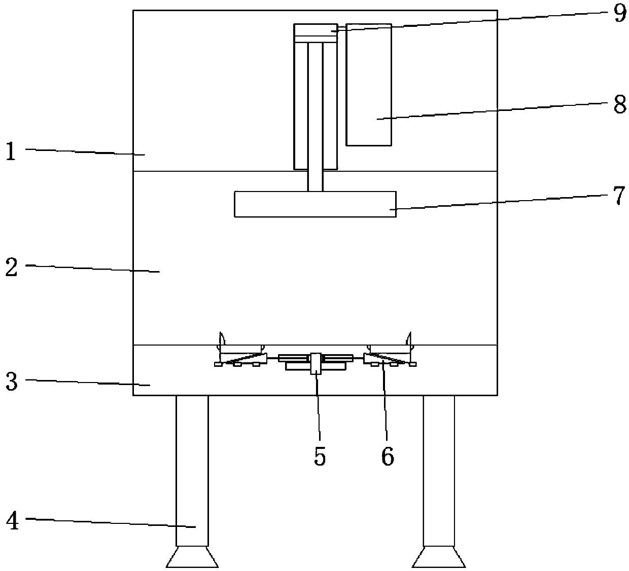
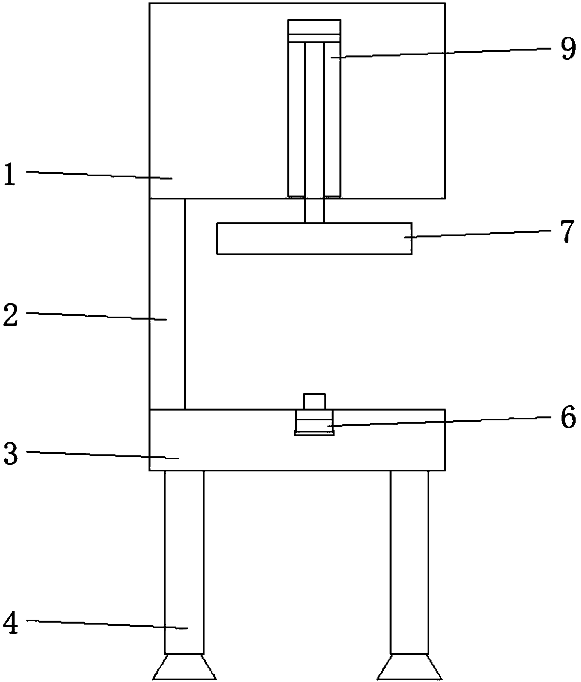
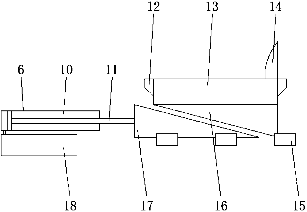
[0020] see Figures 1 to 3 , a kind of embodiment that the present invention provides: stamping machine lifting fixture and its manufacturing process, including stamping box 1, back plate 2, mounting plate 3, support column 4, middle partition plate 5 and lifting fixture 6, the lower end of mounting plate 3 is welded There are support columns 4, four support columns 4 are provided in total, and the four support columns 4 are respectively arranged at the four c...


PUM


Abstract

The invention discloses a lifting clamp for a punch and a manufacturing process thereof. The lifting clamp comprises a punching box, a back plate, a mounting plate, supporting columns, a middle partition plate and lifting clamp bodies; the back plate is mounted at the rear end of the upper end of the mounting plate; the punching box is mounted at the upper end of the back plate; a hydraulic cylinder is mounted in the middle inside the punching box; the middle partition plate is mounted in the middle inside the mounting plate; the lifting clamp bodies are mounted at the two ends of the middle partition plate correspondingly; lifting hydraulic cylinders are mounted at the ends, close to the middle partition plate, of the lifting clamp bodies; lifting hydraulic oil pumps are mounted below thelifting hydraulic cylinders; piston connection rods are slidably mounted inside the lifting hydraulic cylinders; movable triangular prisms are mounted at the output ends of the piston connection rods; lifting triangular prisms are mounted on the sides, away from the lifting hydraulic cylinders, of the movable triangular prisms; and lifting blocks are mounted at the upper ends of the lifting triangular prisms. After punching, punched raw materials are convenient to taken out through the lifting clamp bodies, and large deformation of the raw materials is avoided.

Description

technical field [0001] The invention relates to the technical field of stamping machine mechanical equipment, in particular to a stamping machine lifting fixture and a manufacturing process thereof. Background technique [0002] The punching machine drives the flywheel through the motor, and drives the crank linkage mechanism through the clutch and the transmission gear to move the slider up and down, drives the drawing die to form the steel plate, and uses the driving force of the hydraulic cylinder to make the punching plate squeeze the raw materials to be punched However, the existing punching machine is inconvenient to take out the raw material after stamping, which is very troublesome. If the raw material is taken out forcibly, it may cause damage to the raw material. Therefore, a fixture is needed to push the raw material out. . Contents of the invention [0003] The object of the present invention is to provide a lifting fixture for a stamping machine and its manuf...

Claims


Application Information

Patent Timeline
Patent Type & Authority Applications(China)
IPC IPC(8): B21D22/02B21D45/02
CPCB21D22/02B21D45/02
Inventor 河元福
Owner 天津普越金属制品有限公司
Why Eureka
Try Eureka