Bar clamping mechanism

A technology of clamping mechanism and rod, which is applied in the direction of clamping, metal processing machinery parts, support, etc., can solve the problems of complex structure of manipulator, inconvenient control, low clamping reliability, etc., and achieve simple structure, convenient control, clamping maintain a reliable effect

Inactive Publication Date: 2018-03-23
余姚市奥祥轴承有限公司
View PDF0 Cites 11 Cited by
  • Summary
  • Abstract
  • Description
  • Claims
  • Application Information

AI Technical Summary

Problems solved by technology

However, the manipulator is often complex in structure, inconvenient to control, and the clamping reliability is not high

Method used


Image

  • Bar clamping mechanism
  • Bar clamping mechanism
  • Bar clamping mechanism

Examples


Embodiment Construction

[0014] The present invention will be further described in detail below in conjunction with the accompanying drawings and embodiments.

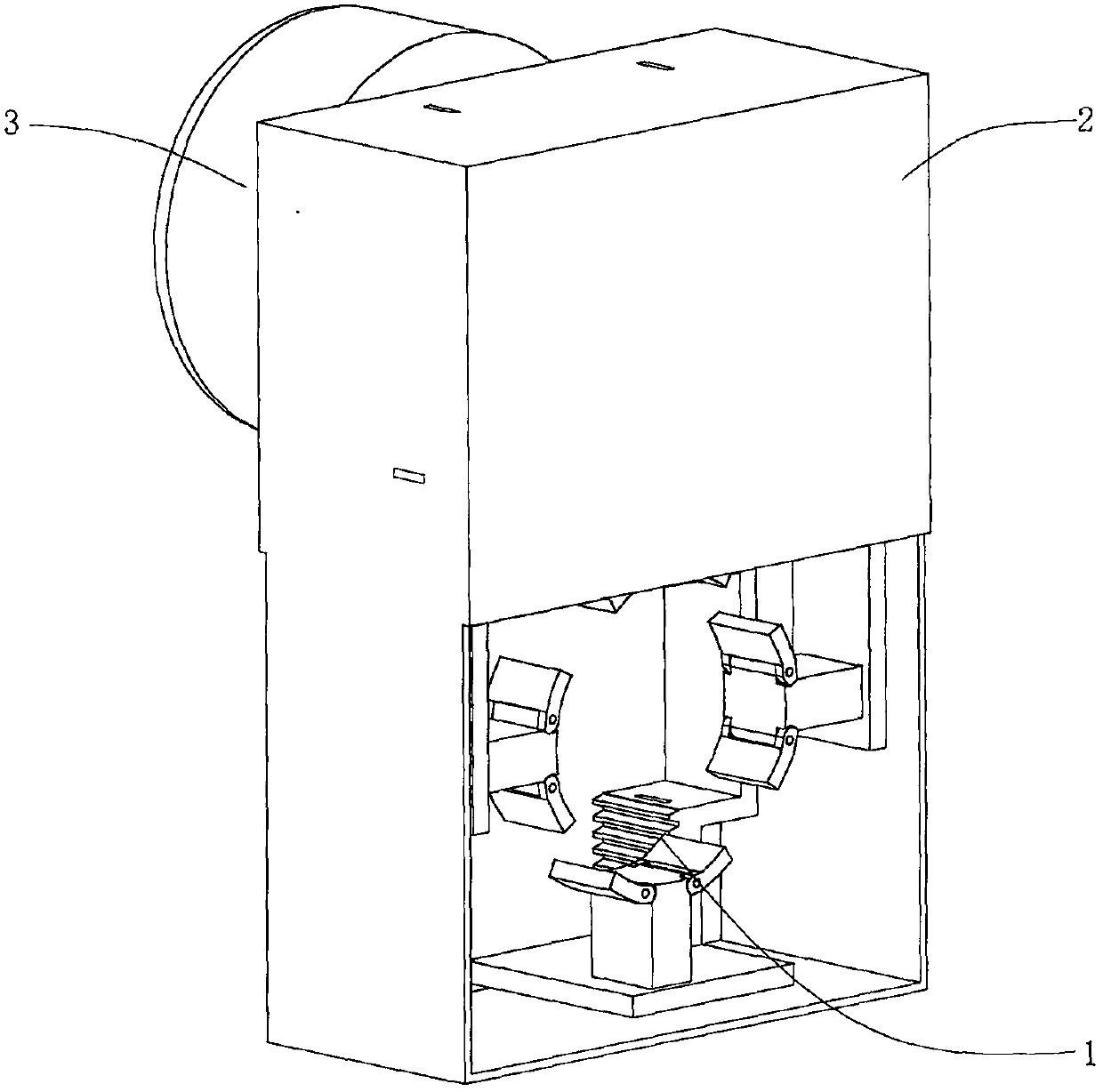
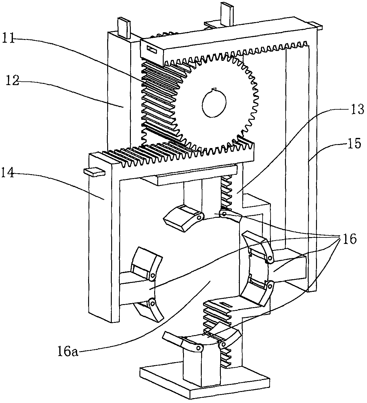
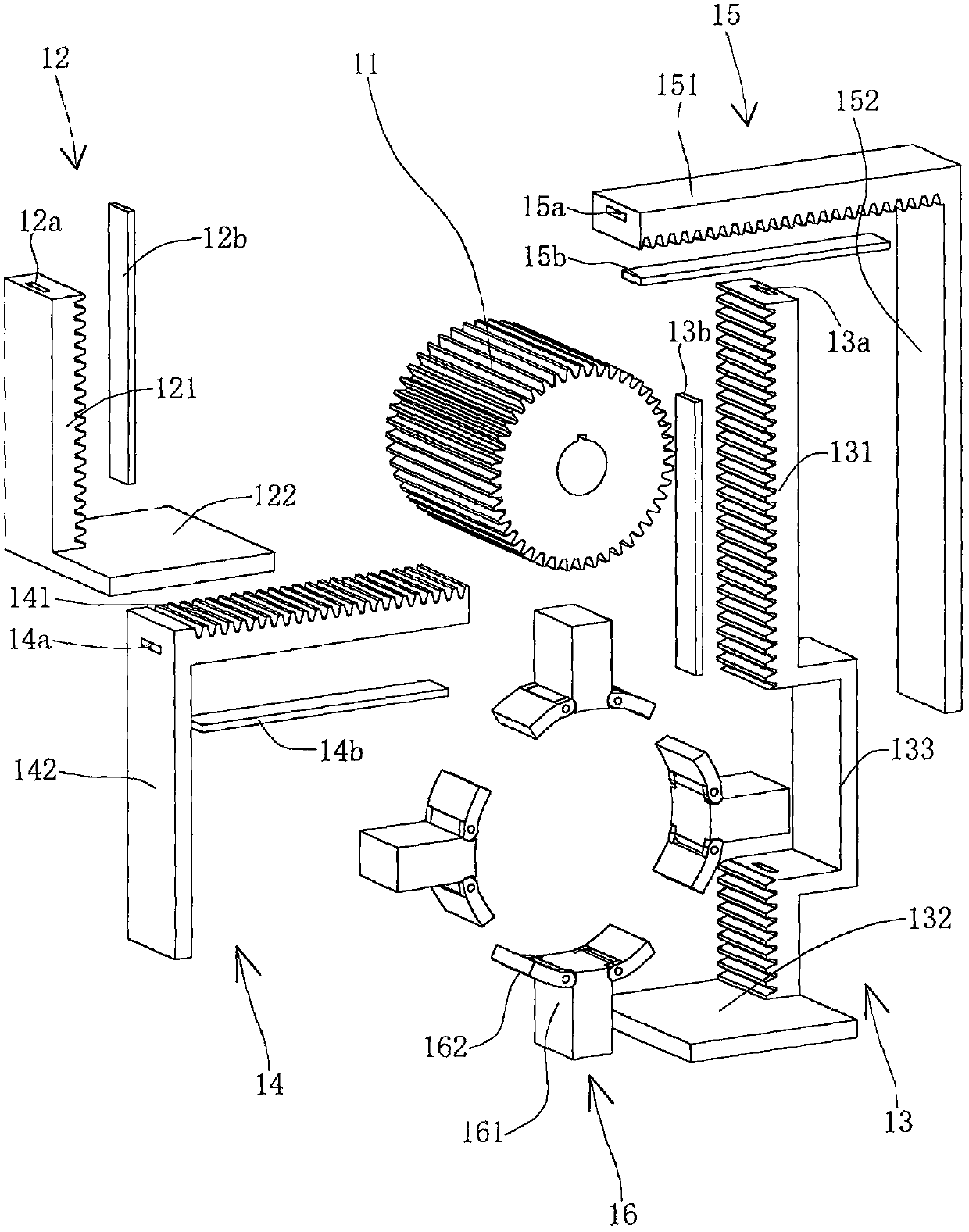
[0015] Such as Figure 1~3 As shown, the bar clamping mechanism of this embodiment includes a clamping part 1, a housing 2 and a motor 3, wherein the clamping part 1 includes a transmission gear 11 connected to the motor 3, and upper clamps that are respectively linked with the transmission gear 11 Holding arm 12, following clamping arm 13, left clamping arm 14, right clamping arm 15, and four clamping hands 16 that are respectively installed on four clamping arms up and down, left and right. The upper clamping arm 12 includes an upper gear part 121 along the vertical direction and an upper mounting plate 122 along the horizontal direction, and the lower clamping arm 13 includes a lower gear part 131 along the vertical direction and a lower mounting plate 132 along the horizontal direction, The left clamping arm 14 includes a left gear part 1...


PUM


Abstract

The invention relates to a bar clamping mechanism, which includes a clamping part, a housing and a driving part, and is characterized in that: the clamping part includes a transmission gear connected with the driving part, and upper clamps respectively linked with the transmission gear Holding arm, lower clamping arm, left clamping arm, right clamping arm, and four clamping hands respectively installed on the above four clamping arms; Four directions constitute a clamping cavity, and the upper clamping arm, the lower clamping arm, the left clamping arm and the right clamping arm can drive the four clamping hands to approach and move away from the clamping arm as the transmission gear rotates. Movement to maintain the center position of the cavity. The rotation of the motor drives the rotation of the transmission gear, and then drives the movement of the four clamping arms up, down, left, and right, and then drives the four clamping hands to perform the clamping action to achieve the purpose of clamping. This bar clamping mechanism has a simple structure , easy to control, reliable clamping and can clamp rods of different diameters.

Description

technical field [0001] The invention relates to the field of screw forming and manufacturing equipment, in particular to a rod clamping mechanism. Background technique [0002] The screw forming machine is a processing and forming machine for rod-shaped fasteners such as bolts and screws, which involves a bar clamping mechanism, which is mainly used to clamp the bar for shearing, feeding and other processes. At present, the manipulator is usually used as the clamping mechanism on the screw forming machine, which imitates the action of human fingers to clamp the bar. However, the manipulator is often complex in structure, inconvenient to control, and has low clamping reliability. [0003] Therefore, how to design a bar clamping mechanism that can clamp the bar more reasonably and reliably is a problem to be solved urgently by those skilled in the art. Contents of the invention [0004] The technical problem to be solved by the present invention is to provide a rod clampin...

Claims


Application Information

Patent Timeline
Patent Type & Authority Applications(China)
IPC IPC(8): B23Q3/06B23G11/00
CPCB23Q3/064B23G11/00
Inventor 周栋
Owner 余姚市奥祥轴承有限公司
Why Eureka
Try Eureka