Sectioning device for silicon crystal rod for electronic element
A technology for electronic components and silicon crystal rods, which is applied in the field of silicon crystal rod cutting devices for electronic components, can solve the problems of inconvenient collection and low cutting efficiency, and achieve the effect of enhancing reliability and safety and avoiding damage
- Summary
- Abstract
- Description
- Claims
- Application Information
AI Technical Summary
Problems solved by technology
Method used
Image
Examples
Embodiment 1
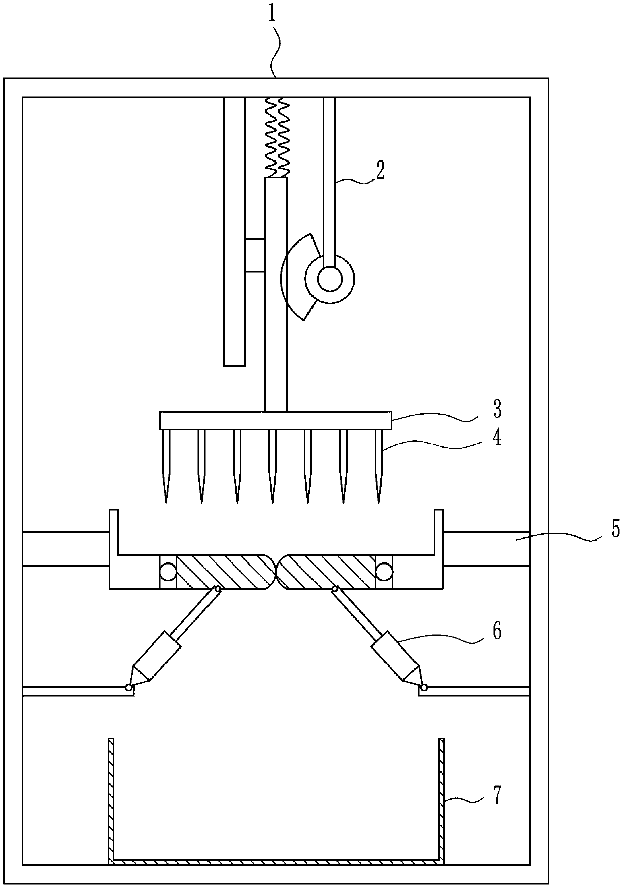
[0036] A silicon crystal bar cutting device for electronic components, such as Figure 1-7 As shown, it includes a frame 1, a lifting mechanism 2, a mounting plate 3, a cutting knife 4, a bracket 5, a blanking mechanism 6 and a collection frame 7. The top of the frame 1 is provided with a lifting mechanism 2, and the bottom of the lifting mechanism 2 is provided with a mounting plate. Plate 3, a cutting knife 4 is installed on the bottom of the mounting plate 3, a support 5 is installed symmetrically in the middle of the left and right side walls in the frame 1, and a blanking mechanism 6 is provided on the support 5, and the blanking mechanism 6 is located on the front of the cutting knife 4. Below, a collection frame 7 is placed in the middle of the inner bottom of the frame 1 .
Embodiment 2
[0038] A silicon crystal bar cutting device for electronic components, such as Figure 1-7 As shown, it includes a frame 1, a lifting mechanism 2, a mounting plate 3, a cutting knife 4, a bracket 5, a blanking mechanism 6 and a collection frame 7. The top of the frame 1 is provided with a lifting mechanism 2, and the bottom of the lifting mechanism 2 is provided with a mounting plate. Plate 3, a cutting knife 4 is installed on the bottom of the mounting plate 3, a support 5 is installed symmetrically in the middle of the left and right side walls in the frame 1, and a blanking mechanism 6 is provided on the support 5, and the blanking mechanism 6 is located on the front of the cutting knife 4. Below, a collection frame 7 is placed in the middle of the inner bottom of the frame 1 .
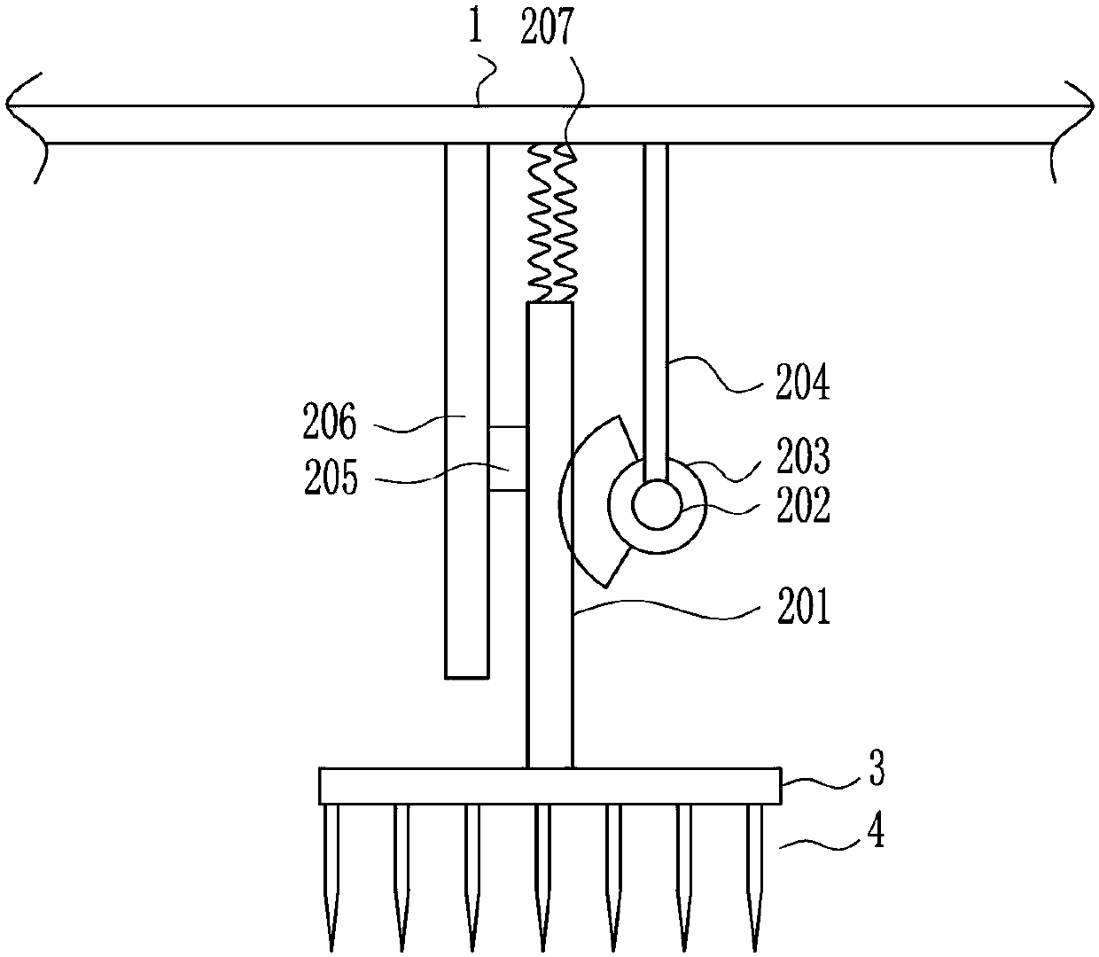
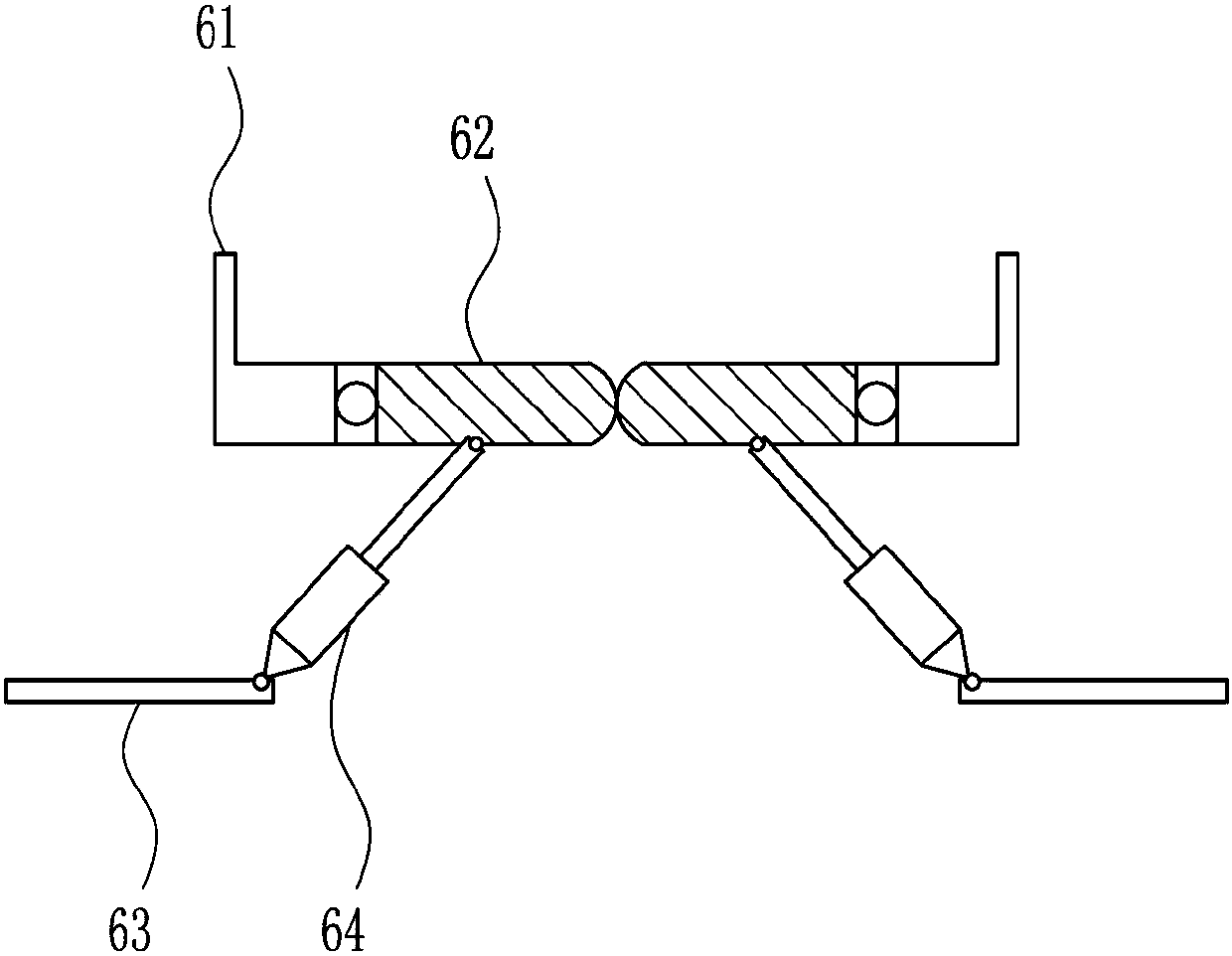
[0039] The lifting mechanism 2 includes a rack 201, a motor 202, a sector gear 203, a pole 204, a vertical slider 205, a vertical slide rail 206 and a spring 207, and the top of the frame 1 is prov...
Embodiment 3
[0041] A silicon crystal bar cutting device for electronic components, such as Figure 1-7 As shown, it includes a frame 1, a lifting mechanism 2, a mounting plate 3, a cutting knife 4, a bracket 5, a blanking mechanism 6 and a collection frame 7. The top of the frame 1 is provided with a lifting mechanism 2, and the bottom of the lifting mechanism 2 is provided with a mounting plate. Plate 3, a cutting knife 4 is installed on the bottom of the mounting plate 3, a support 5 is installed symmetrically in the middle of the left and right side walls in the frame 1, and a blanking mechanism 6 is provided on the support 5, and the blanking mechanism 6 is located on the front of the cutting knife 4. Below, a collection frame 7 is placed in the middle of the inner bottom of the frame 1 .
[0042] The lifting mechanism 2 includes a rack 201, a motor 202, a sector gear 203, a pole 204, a vertical slider 205, a vertical slide rail 206 and a spring 207, and the top of the frame 1 is prov...
PUM
 Abstract
Description
Claims
Application Information
 - R&D Engineer
- R&D Manager
- IP Professional
- Industry Leading Data Capabilities
- Powerful AI technology
- Patent DNA Extraction
Browse by: Latest US Patents, China's latest patents, Technical Efficacy Thesaurus, Application Domain, Technology Topic, Popular Technical Reports.
© 2024 PatSnap. All rights reserved.Legal|Privacy policy|Modern Slavery Act Transparency Statement|Sitemap|About US| Contact US: help@patsnap.com


