Wear-resisting metal hydraulic baling press

A wear-resistant, metal technology, applied in the field of balers, can solve the problems of difficult movement, high labor intensity and large workload, and achieve the effects of improving work efficiency, reducing labor intensity and improving service life.

Pending Publication Date: 2018-03-23
张旋
View PDF8 Cites 2 Cited by
  • Summary
  • Abstract
  • Description
  • Claims
  • Application Information

AI Technical Summary

Problems solved by technology

[0002] Today's metal hydraulic balers are used in many industries such as building materials and metallurgy. The process of pushing metal materials into the metal hydraulic baler box is easy to cause internal box wear, and the material will leak out after wearing through the box.
Existing cabinets generally have an integral structure, and to replace the inner panel of the cabinet, the hydraulic device needs to be disassembled from the cabinet, and then the whole cabinet can be disassembled to replace the worn parts of the cabinet. The replacement work is difficult and the workload is large
[0003] At present, the packaging device slows down wear by installing wear-resistant plates inside the material box. When replacing wear-resistant plates, it is necessary to cut off the wear-resistant plates and then weld new wear-resistant plates in place. The process is complicated and labor-intensive
At the same time, the object is in direct contact with the wear-resistant plate, the wear-resistant plate is seriously worn and the service life is not long, and the object is not easy to move on the upper part of the wear-resistant plate, which aggravates the wear of the wear-resistant plate

Method used


Image

  • Wear-resisting metal hydraulic baling press
  • Wear-resisting metal hydraulic baling press

Examples


Embodiment Construction

[0015] The following will clearly and completely describe the technical solutions in the embodiments of the present invention with reference to the accompanying drawings in the embodiments of the present invention. Obviously, the described embodiments are only some, not all, embodiments of the present invention. Based on the embodiments of the present invention, all other embodiments obtained by persons of ordinary skill in the art without making creative efforts belong to the protection scope of the present invention.

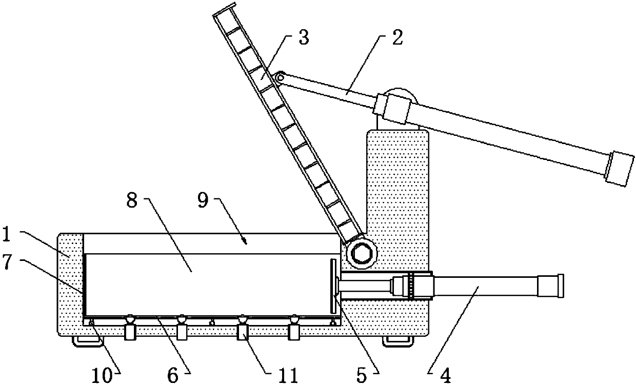
[0016] see figure 1 , figure 1 It is a structural schematic diagram of the present invention, a wear-resistant metal hydraulic baler, which includes a body 1 and a flip cover 3, a rotating shaft is installed in the installation position inside the body on one side of the body 1, and the connection on the upper part of the rotating shaft body The position is fixedly connected to the flip cover 3 by fixing bolts, and the connecting ears welded and fixed in the ...


PUM


Abstract

The invention discloses a wear-resisting metal hydraulic baling press which comprises a machine body and a turnover cover. A connecting lug which is fixedly welded to the middle of the upper surface of a turnover cover body is connected with the tail end of an inner rod of a turnover cover hydraulic pillar through a pin. The middle part of a turnover cover hydraulic pillar body is installed in aninstallation site on the upper portion of one side of the machine body through a rotating shaft. A material box is arranged at the side, far away from the turnover cover, of the inside of the machinebody. The tail end of an inner rod of a longitudinal hydraulic pillar body is connected with a pushing plate through a set bolt. A bottom wear-resisting plate is installed at the bottom of the material box. A side wear-resisting plate is vertically installed at the side, far away from the pushing plate, of the inside of the material box. Long wear-resisting plates are installed at the two sides, far away from the pushing plate and the side wear-resisting plate, of the inside of the material box. Sliders are installed in installation sites arranged at the bottom of the machine body. According to the wear-resisting metal hydraulic baling press, rolling balls on the upper portions of the sliders make contact with the bottom of a material so that the material can be moved smoothly, and internal abrasion of the device is reduced.

Description

technical field [0001] The invention belongs to the technical field of balers, and in particular relates to a wear-resistant metal hydraulic baler. Background technique [0002] Today's metal hydraulic balers are used in many industries such as building materials and metallurgy. The process of pushing metal materials into the metal hydraulic baler box is easy to cause internal box wear, and the material will leak out after wearing through the box. Existing cabinets generally have an integral structure, and to replace the inner panel of the cabinet, the hydraulic device needs to be disassembled from the cabinet, and then the whole cabinet can be disassembled to replace the worn parts of the cabinet. The replacement work is difficult and the workload is heavy. [0003] At present, the packaging device slows down wear by installing wear-resistant plates inside the material box. When replacing wear-resistant plates, it is necessary to cut off the wear-resistant plates and then w...

Claims


Application Information

Patent Timeline
Patent Type & Authority Applications(China)
IPC IPC(8): B30B9/30
CPCB30B9/3032B30B9/3057
Inventor 张旋
Owner 张旋
Why Eureka
Try Eureka