
Bill transport mechanism of highway toll station sentry box

A technology of high-speed toll station and conveying mechanism, applied in the direction of conveyor, conveyor object, object supply, etc., can solve the problem of long distance between toll booth and toll vehicle.

Inactive Publication Date: 2018-03-23
蔡晓锋
View PDF2 Cites 1 Cited by
  • Summary
  • Abstract
  • Description
  • Claims
  • Application Information

AI Technical Summary

Problems solved by technology

[0011] In order to solve the above-mentioned technical problems, the present invention provides a bill transmission mechanism of a sentry box at a high-speed toll station, to solve the problem that the distance between the toll booth and the toll vehicle is too far when the existing domestic toll roads use a passing IC card and cash to be manually issued by a toll collector. The problem that the driver needs to get out of the car to pay the toll

Method used


Image

  • Bill transport mechanism of highway toll station sentry box
  • Bill transport mechanism of highway toll station sentry box
  • Bill transport mechanism of highway toll station sentry box

Examples


Embodiment

[0034] as attached figure 1 to attach Figure 8 Shown:

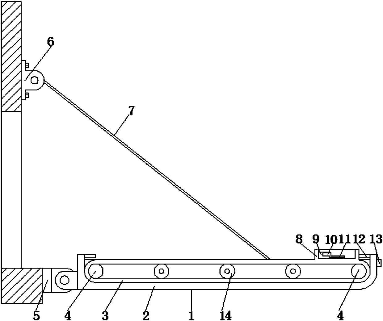
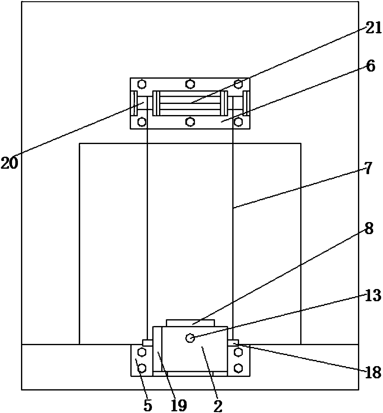
[0035] The invention provides a ticket transmission mechanism for a sentry box at a high-speed toll station, which includes a device body 1, a rotating cantilever 2, a conveyor belt 3, a transmission motor 4, a rotary base 5, a lifting base 6, a steel wire rope 7, an item placement cylinder 8, a clamping Block 9, clamping plate 10, rubber pad 11, limit switch 12, driver operation switch 13, support cylindrical roller 14, bearing 15, transmission motor spindle 16, rotation mounting block 17, wire rope mounting block 18, side baffle 19 , a winding roller 20, a lifting motor 21 and a fixed inner cavity 22, the bottom of the device body 1 is provided with a rotating cantilever 2, and the top of the rotating cantilever 2 is provided with a fixed inner cavity 22; Stroke switch 12, and the top center of the right end of the rotating cantilever 2 is equipped with a driver's operation switch 13 through a screw; the bottom of th...


PUM


Abstract

The invention provides a ticket transmission mechanism for a sentry box at a high-speed toll station, which includes a lifting motor and a fixed inner cavity. The bottom of the device body is provided with a rotating cantilever, and the top of the rotating cantilever is provided with a fixed inner cavity; the left and right sides of the top of the rotating cantilever The inner wall of the center is equipped with travel switches through screws, and the top center of the right end of the rotating cantilever is equipped with a driver's operation switch through screws; the bottom of the center of the left end of the rotating cantilever is provided with a rotating mounting block, and the rotating mounting block is installed on the left side through a fixed shaft. Inside the rotating base; the right side of the rotating base is provided with a semicircular fixed mounting plate, and the rotating base is fixed and installed on the protrusion below the window of the sentry box through front and rear bolts. The setting of the rotating cantilever is conducive to the adjustment of the position according to the height of the toll vehicle. It will not cause the toll booth to pay the toll because the distance between the toll booth and the toll vehicle is too far and the height difference is too large. This ensures the safety of the driver and reduces the trouble .

Description

technical field [0001] The invention belongs to the technical field of high-speed toll auxiliary facilities, and in particular relates to a ticket transmission mechanism for a sentry box of a high-speed toll station. Background technique [0002] Toll stations refer to traffic facilities built to collect vehicle tolls, usually including toll gates, toll islands, toll booths, toll lanes, awnings, toll machinery, toll plazas and toll booths. Since then until now, most of the first-class roads and expressways in mainland China have toll booths. Previously, most of the toll booths used manual toll collection. [0003] After entering the 21st century, with the development of ETC technology, most of today's toll stations adopt a combination of manual toll collection and ETC technology to increase the efficiency of motor vehicles. [0004] For example, application number 201210179878.7 discloses a ticket storage and control device for expressway toll stations. It is fixed with a ...

Claims


Application Information

Patent Timeline
IPC IPC(8): B65G25/06B65G41/00B65H5/04
CPCB65G25/06B65G41/002B65H5/04B65H2404/20B65H2701/1912B65H2701/1914
Inventor 蔡晓锋
Owner 蔡晓锋
Learn More