Clarifying device and clarifying method for glass

A clarification device and glass technology, which is applied in the field of optical glass manufacturing, can solve the problems of large expansion and contraction changes of the clarification tank, easy damage to the platinum structure, unfavorable energy saving and consumption reduction, etc., so as to facilitate floating and overflow, reduce energy consumption, and reduce volume Effect

Inactive Publication Date: 2018-03-23
HUBEI NEW HUAGUANG NEW INFORMATION MATERIALS CO LTD
View PDF3 Cites 3 Cited by
  • Summary
  • Abstract
  • Description
  • Claims
  • Application Information

AI Technical Summary

Problems solved by technology

The clarification tank of commonly used optical glass is generally made of platinum or platinum alloy. The clarification tank is generally in a circular or U-shaped structure. Due to the relatively long structure of the clarification tank, the linear expansion causes a large amount of expansion and contraction of the clarification tank during the heating and cooling process. It is easy to damage the platinum structure and cause the leakage of glass liquid
In addition, to increase the clarification ability of the glass liquid, the clarification tank needs to be long enough and wide enough, so that the space occupation is relatively large and the heat loss is large, so the heating power is high, which is not conducive to energy saving and consumption reduction.

Method used


Image

  • Clarifying device and clarifying method for glass

Examples


Embodiment Construction

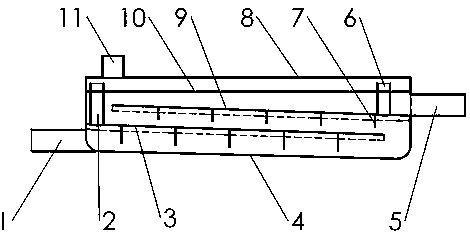
[0023] Such as figure 1 shown. A glass clarification device structure of the present invention includes an inlet pipe 1, a front exhaust pipe 2, a lower partition 3, a clarification tank 4, an outlet pipe 5, a rear exhaust pipe 6, a baffle 7, a tank cover 8, and an upper partition 9 and chimney11. The clarification tank 4 is a cuboid or U-shaped tank-shaped cavity with a tank cover. The inlet pipe 1 and the outlet pipe 5 are respectively welded at the front and rear ends, and are used as channels for the inflow and outflow of glass liquid. The lower dividing plate 3 and the upper dividing plate 9 are folded along the length direction into an arc or an inverted V shape with high middle part and low sides. The upper partitions 9 are respectively welded on three sides of the walls of the clarification tank 4 to form a multi-layer separation layer and extend the flow path of the glass liquid in the clarification tank 4 . The top of one end of the lower partition 3 and the upper...


PUM


Abstract

The invention provides a clarifying device and a clarifying method for glass, belonging to the technical field of manufacturing of optical glass. The invention is to solve the problems of excessivelylong clarifying groove, easy damage of a platinum product and low clarifying efficiency for optical glass. The clarifying device is mainly characterized by comprising an inlet pipe, a clarifying groove, an outlet pipe and a chimney, wherein the clarifying groove is a cavity with a cuboid shape or a covered U-shaped groove shape; the front end and the rear end of the clarifying groove are respectively welded with the inlet pipe and the outlet pipe which are respectively used as an inflow channel and an outflow channel for liquid glass; the interior of the clarifying groove is provided with partition plates which are used for up-down separation, so independent separate layers with a plurality of layers in communication are formed, and the flowing route of the liquid glass in the clarifying groove is prolonged; a groove cover and the clarifying groove are seal-welded; and the chimney is arranged at the top part of the clarifying groove and used for discharging gas in the clarifying groove. The clarifying device provided by the invention has the characteristics of high efficiency and small size, and is mainly used for clarifying the optical glass.

Description

technical field [0001] The invention belongs to the technical field of optical glass manufacturing. In particular, the invention relates to a clarification device and a clarification method of optical glass. Background technique [0002] The glass manufacturing process is mainly composed of three parts: melting, clarification and homogenization. The main function of the clarification tank in the furnace structure is to eliminate air bubbles. Therefore, the clarification tank in the furnace structure is more important. The design of the clarification tank directly determines the elimination of optical glass bubbles. ability. [0003] Because optical glass has higher requirements on air bubbles, the structure of clarification tanks is generally relatively large. The clarification tank of commonly used optical glass is generally made of platinum or platinum alloy. The clarification tank is generally in a circular or U-shaped structure. Due to the relatively long structure of ...

Claims


Application Information

Patent Timeline
Patent Type & Authority Applications(China)
IPC IPC(8): C03B5/225
CPCC03B5/225
Inventor 姜敬陆徐华峰徐光以梁立新
Owner HUBEI NEW HUAGUANG NEW INFORMATION MATERIALS CO LTD
Why Eureka
Try Eureka