Construction method of pile foundation test well
A pile foundation and wellbore technology, applied in well sinking, mining equipment, earthwork drilling, etc., can solve the problems of large investment, inconvenient maintenance, long construction period of test wells, etc., and achieve low operating costs, reduced construction costs, and supporting The effect of low capital
- Summary
- Abstract
- Description
- Claims
- Application Information
AI Technical Summary
Problems solved by technology
Method used
Image
Examples
Embodiment 1
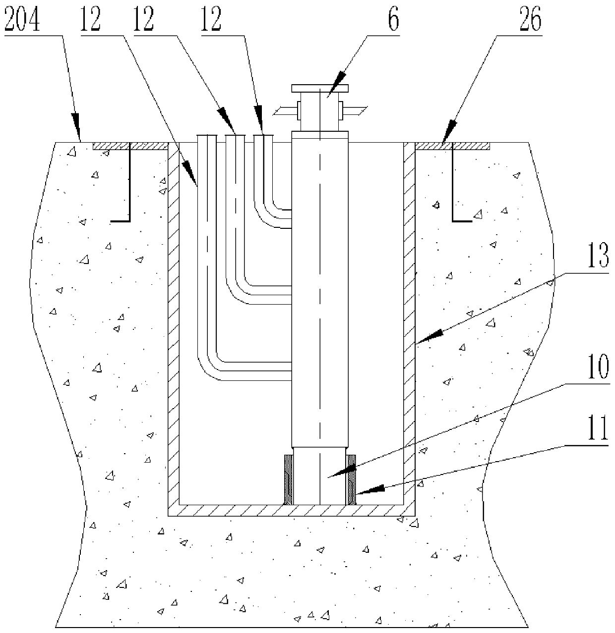
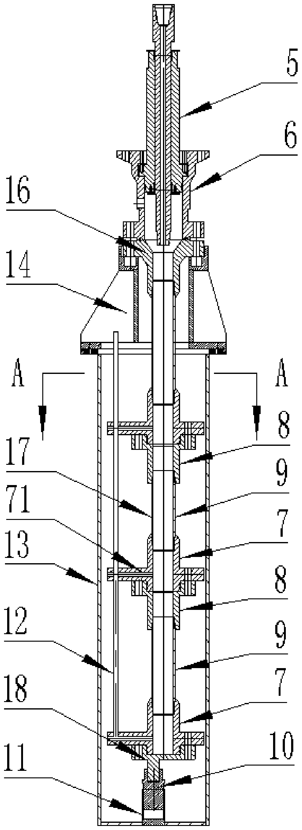
[0048] In this embodiment, the pile-based test well may be a vertical normal temperature test well, and the suitable operating temperature range is 25°C to 120°C. The test outer wellbore contains a support 14 connected up and down and an outer casing 13. The outer diameter of the outer casing 13 matches the diameter of the wellbore. The outer diameter of the outer casing 13 is 660mm, and the depth of the outer casing 13 is 20m. The upper end of 13 is provided with a wellhead embedded part 26, the outer casing 13 is a pipe string structure with an open upper end and a closed lower end, and the support 14 is a cylindrical structure with open upper and lower ends. In step 3, the test inner wellbore The upper end is suspended on the upper end of the support 14, such as Figure 3 to Figure 6 shown.
[0049] In this embodiment, the support 14 is located above the ground 104, and the support 14 is a cylindrical structure. The support 14 includes a top ring 141, a vertical tube 142 a...
Embodiment 2
[0058] In this embodiment, the pile-based test well may be a vertical high-temperature test well, and the suitable operating temperature range is 25°C to 350°C. The wellhead device includes a hollow tube 5 and a wellhead tee 6 which are sequentially sleeved from the inside to the outside. The hollow tube 5 and the wellhead tee 6 are in an upright state, and the hollow tube 5 is sequentially sleeved with a preload disc 19, Compression cover 20 and sealing ring, compression cover 20 and described sealing ring are all positioned between hollow cylinder 5 and wellhead tee 6, and compression cover 20 can compress described sealing ring to make hollow cylinder 5 and wellhead tee 6 seal between them.
[0059] In this embodiment, the upper end of the compression cover 20 and the pre-tightening disc 19 are located above the wellhead tee 6, the compression cover 20 can move up and down relative to the hollow tube 5, and the pre-tightening disc 19 is screwed to the hollow tube 5 , along...
PUM
 Abstract
Description
Claims
Application Information
 - R&D
- Intellectual Property
- Life Sciences
- Materials
- Tech Scout
- Unparalleled Data Quality
- Higher Quality Content
- 60% Fewer Hallucinations
Browse by: Latest US Patents, China's latest patents, Technical Efficacy Thesaurus, Application Domain, Technology Topic, Popular Technical Reports.
© 2025 PatSnap. All rights reserved.Legal|Privacy policy|Modern Slavery Act Transparency Statement|Sitemap|About US| Contact US: help@patsnap.com


