
Desktop bracket

A desktop, connecting piece technology, applied in the field of brackets, can solve the problems of large effort, automatic lift, small bearing range, etc., to achieve the effect of increasing the weight range, avoiding torsion, and supporting high strength

Pending Publication Date: 2018-03-23
KUNSHAN HONGJIE ELECTRONICS CO LTD
View PDF0 Cites 3 Cited by
  • Summary
  • Abstract
  • Description
  • Claims
  • Application Information

AI Technical Summary

Problems solved by technology

[0002] Mounting brackets for electronic equipment, such as monitor brackets, TV brackets, projector brackets, etc. At present, many electronic equipment are installed on desktops and other workbenches through mounting brackets, which is convenient for staff to operate electronic equipment on the brackets. The height adjustment of the upper bracket electronic products is adjusted by swinging the arm up and down or connected with the column through the sliding sleeve through the gasket clamping method to achieve height adjustment. The adjustment is inconvenient and the stability is poor. The general adjustment mechanism For the bolts installed on the base, through the rotation of the bolts, the nuts connected with them are driven up and down, and then the length and angle of the triangle formed by the bolts, elastic parts and one side of the swing arm are changed to achieve stable positioning at different heights. The load-bearing range of the mechanism is small, and the weighing range is generally 2-9kg. When there is no electronic equipment hanging up, it will automatically rise. It takes a lot of effort to adjust, and the adjustment is not smooth.

Method used


Image

  • Desktop bracket
  • Desktop bracket
  • Desktop bracket

Examples


Embodiment

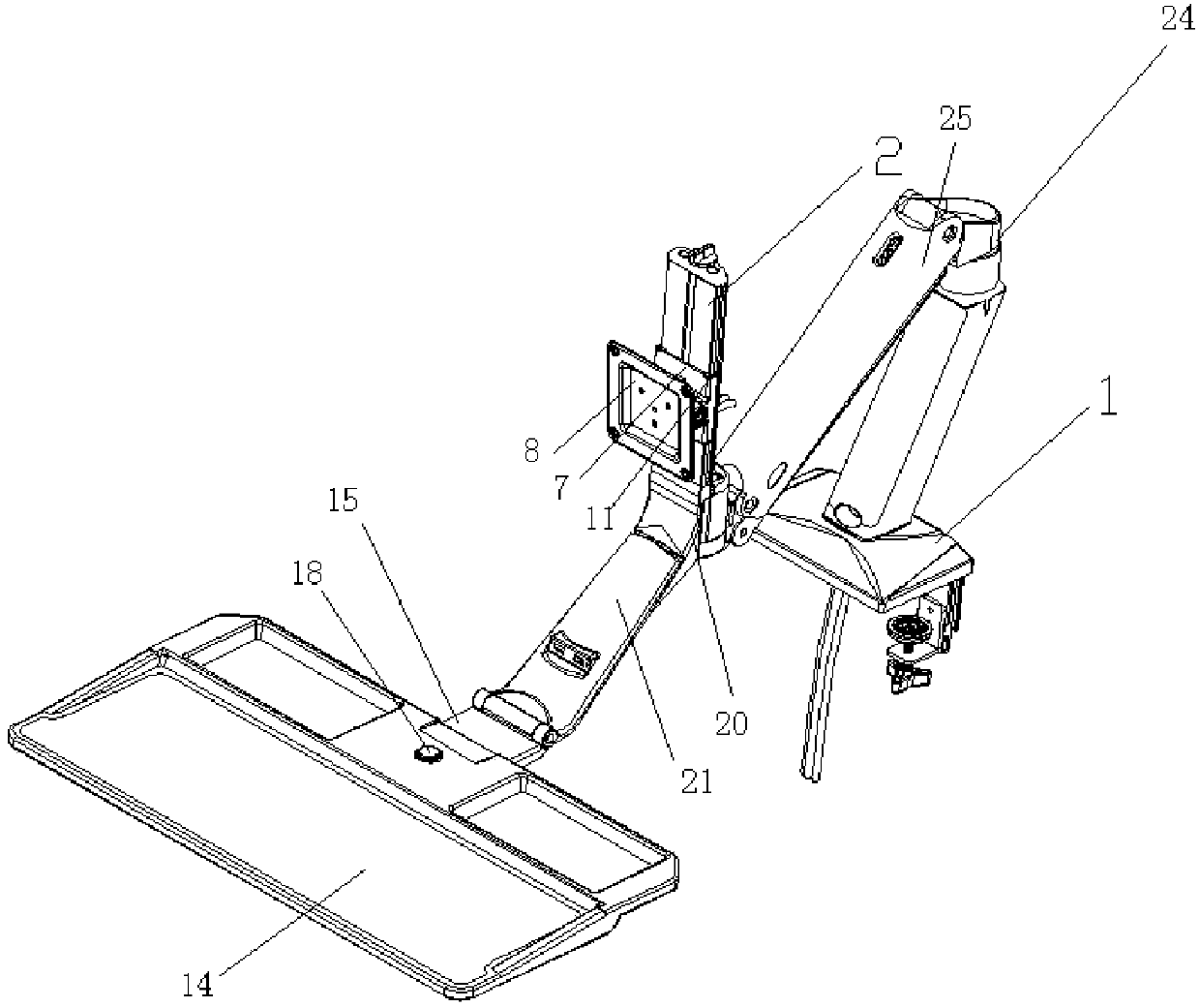
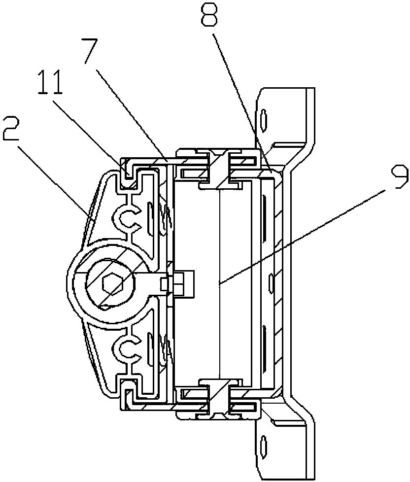
[0028] Embodiment: a table-top bracket 28, including a base 1, an arm mechanism and an equipment installation device, the base 1 can be detachably and fixedly installed on the desktop, and the arm mechanism includes an arm front connector 23, an arm rear connector 24, Upper support 25, lower support 26, adjustment device and elastic support device 27, the rear connector 24 of the arm is installed on the base 1, the equipment installation device is installed on the front connector 23 of the arm, the front connector 23 of the arm, the upper support 25 1. The arm rear connector 24 and the lower support 26 are hinged one by one to form a parallelogram structure. The upper and lower ends of the adjustment device are hingedly connected with the upper support 25 and the lower support 26 respectively, and the two ends of the elastic support device 27 are connected with the adjustment device and the upper support respectively. 25, the length of the elastic support device 27 can be elast...


PUM


Abstract

The invention discloses a desktop bracket. The desktop bracket comprises a base, an arm mechanism and an equipment mounting device, wherein the base is detachably fixedly mounted on a desktop; the armmechanism comprises an arm front connecting piece, an arm back connecting piece, an upper support, a lower support, an adjusting device and an elastic supporting device; the arm back connecting pieceis mounted on the base; the equipment mounting device is mounted on the arm front connecting piece; the arm front connecting piece, the upper support, the arm back connecting piece and the lower support are sequentially hinged to form a parallelogram structure; the upper and lower ends of the adjusting device are hinged to the upper support and the lower support separately; the two ends of the elastic supporting device are connected with the adjusting device and the upper support separately; and the elastic supporting device can elastically extend and retract. According to the desktop bracket, adjustment is convenient and effort-saving, the weight range of hung electronic equipment is large, the mounting height and elevation angle positions of electronic equipment are stable, a tray can be guaranteed to be in the horizontal state, adjustment is convenient, and a user is comfortable when utilizing the desktop bracket.

Description

technical field [0001] The invention relates to a support, in particular to a table-top support. Background technique [0002] Mounting brackets for electronic equipment, such as monitor brackets, TV brackets, projector brackets, etc. At present, many electronic equipment are installed on desktops and other workbenches through mounting brackets, which is convenient for staff to operate electronic equipment on the brackets. The height adjustment of the upper bracket electronic products is adjusted by swinging the arm up and down or connected with the column through the sliding sleeve through the gasket clamping method to achieve height adjustment. The adjustment is inconvenient and the stability is poor. The general adjustment mechanism For the bolts installed on the base, through the rotation of the bolts, the nuts connected with them are driven up and down, and then the length and angle of the triangle formed by the bolts, elastic parts and one side of the swing arm are cha...

Claims


Application Information

Patent Timeline
IPC IPC(8): F16M13/02F16M11/06F16M11/18F16M11/16
CPCF16M11/06F16M11/16F16M11/18F16M13/02F16M2200/041
Inventor 常晓杰
Owner KUNSHAN HONGJIE ELECTRONICS CO LTD
Learn More