Test tube drying device

A drying device and test tube technology, applied in the directions of drying, drying machine, drying gas arrangement, etc., can solve the problems of uneven heating of the inner tube wall, affecting the drying effect, limited spray range, etc. The effect of uniform heating and improved spray range

Inactive Publication Date: 2018-03-23
HUNAN HUIXUN ENTERPRISE MANAGEMENT CO LTD
View PDF4 Cites 3 Cited by
  • Summary
  • Abstract
  • Description
  • Claims
  • Application Information

AI Technical Summary

Problems solved by technology

These equipments often need to be used immediately after washing. Since there is water left on the equipment after washing, it will affect the use. At present, the commonly used test tube drying device is to spray hot air to the inner wall of the test tube to achieve the purpose of drying.
[0003] However, when the existing test tube drying device sprays hot air, the hot air is mostly sprayed on the inner tube wall of the test tube, and the spraying range is limited, so it is easy to cause uneven heating of the inner tube wall of the test tube, thereby affecting the drying effect.

Method used


Image

  • Test tube drying device
  • Test tube drying device
  • Test tube drying device

Examples


Embodiment Construction

[0020] The following will clearly and completely describe the technical solutions in the embodiments of the present invention with reference to the accompanying drawings in the embodiments of the present invention. Obviously, the described embodiments are only some, not all, embodiments of the present invention. Based on the embodiments of the present invention, all other embodiments obtained by persons of ordinary skill in the art without making creative efforts belong to the protection scope of the present invention.

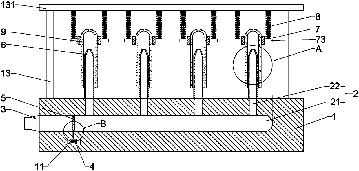
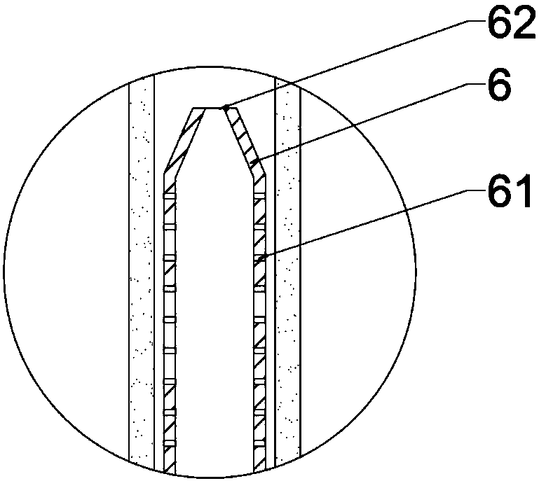
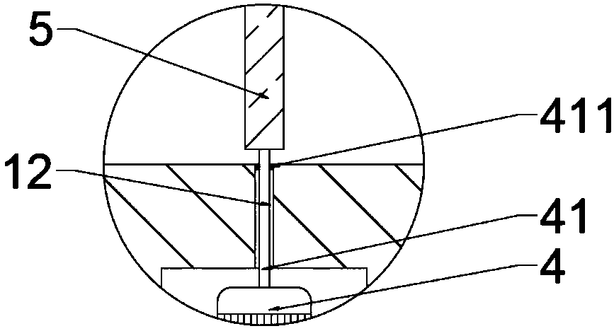
[0021] see Figure 1~5 , in an embodiment of the present invention, a test tube drying device includes a base 1, an air flow channel 2, a motor 4, a baffle plate 5, an air pipe 6 and a clamping device 7; an air flow channel 2 is opened in the base 1, The air flow channel 2 is composed of a main channel 21 and a plurality of branch channels 22 communicated with the main channel 21. The branch channels 22 are perpendicular to the main channel 21. The outlet of t...


PUM


Abstract

The invention discloses a test tube drying device comprising a base, an airflow channel, a motor, a baffle, air tubes and clamping devices. The airflow channel is formed in the base and comprises a main channel and a plurality of branch channels communicating with the main channel. The multiple air tubes are vertically arranged at the top of the base and are designed to be open at the two ends, wherein lower openings communicate with outlets of the branch channels. Air holes are evenly distributed in the side tube walls of the air tubes. The multiple clamping devices are arranged, are in one-to-one correspondence with the air tubes, are located below a top plate, and are connected with the top plate through elastic connecting parts. A cavity is formed in the base and communicates with themain channel through a pierced hole. The motor is installed in the cavity. The output end of the motor is connected with a transmission shaft. The transmission shaft goes deep into the main channel from the pierced hole and is connected with the baffle. According to the test tube drying device, point spraying of hot airflow is converted into face spraying, thus the inner tube wall of a test tube is heated more evenly, and the drying effect is ensured.

Description

technical field [0001] The invention relates to a drying device, in particular to a test tube drying device. Background technique [0002] The test tube dryer is a multi-functional desktop air dryer, which can be used in the laboratory, especially for the rapid drying and heating of flasks, test tubes, measuring cups, distillation devices, glass slides, etc. used in medical and chemical research. These equipments often need to be used immediately after washing, because after washing, there is residual water on the equipment, which affects the use. At present, the commonly used test tube drying device is to spray hot air to the inner wall of the test tube to achieve the purpose of drying. [0003] However, when the existing test tube drying device sprays hot air, the hot air is mostly sprayed on the inner tube wall of the test tube, and the spraying range is limited, so it is easy to cause uneven heating of the inner tube wall of the test tube, thereby affecting the drying ef...

Claims


Application Information

Patent Timeline
Patent Type & Authority Applications(China)
IPC IPC(8): F26B9/04F26B21/00F26B21/12F26B25/02F26B25/04F26B25/00
CPCF26B9/04F26B21/004F26B21/12F26B25/008F26B25/02F26B25/04
Inventor 金雄
Owner HUNAN HUIXUN ENTERPRISE MANAGEMENT CO LTD
Why Eureka
Try Eureka