
Real-time object three-dimensional reconstruction method based on depth camera

A technology of depth camera and 3D reconstruction, applied in the field of 3D imaging, can solve the problems of high segmentation complexity, huge data volume of depth camera, and decreased accuracy of 3D object model.

Active Publication Date: 2018-03-23
ZHEJIANG UNIV
View PDF4 Cites 40 Cited by
  • Summary
  • Abstract
  • Description
  • Claims
  • Application Information

AI Technical Summary

Problems solved by technology

[0004] The core issues of 3D reconstruction based on depth cameras are: 1. The data volume of depth cameras is very large, how to deal with huge data in the reconstruction process
[0008] 1. The object or person is not separated from the scene. When the reconstructed object is an object or person in the scene, the object needs to be segmented in the reconstructed 3D model. The complexity of segmentation is high, so it is not suitable for reconstructing the object For the case of objects or people in the scene
[0009] 2. Since the frame rate of the camera is fixed, when the scanning speed is fast, the camera poses of the two frames before and after are quite different, resulting in the failure of the ICP+RGBD matching algorithm used by KinectFusion and Kintinuous
[0010] 3. Accumulated errors lead to a decline in the accuracy of the 3D object model. Although loopback detection has been added to Kintinuous and can effectively detect loopbacks and perform loopback optimization to correct the model during scene reconstruction, this loopback detection method often fails during human body scanning. Wrong loopback or no loopback occurs

Method used


Image

  • Real-time object three-dimensional reconstruction method based on depth camera
  • Real-time object three-dimensional reconstruction method based on depth camera
  • Real-time object three-dimensional reconstruction method based on depth camera

Examples


Embodiment Construction

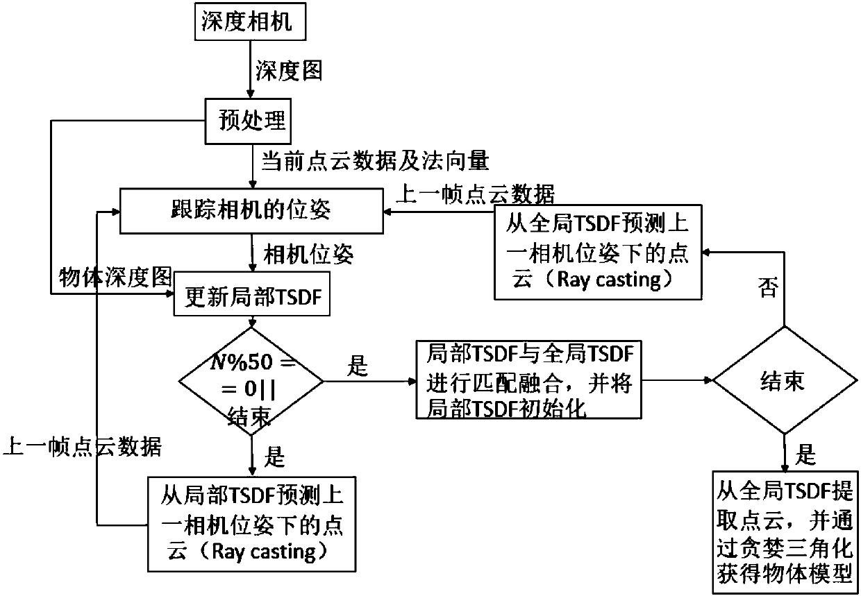
[0058] The overall flow of the object 3D reconstruction algorithm is as follows:

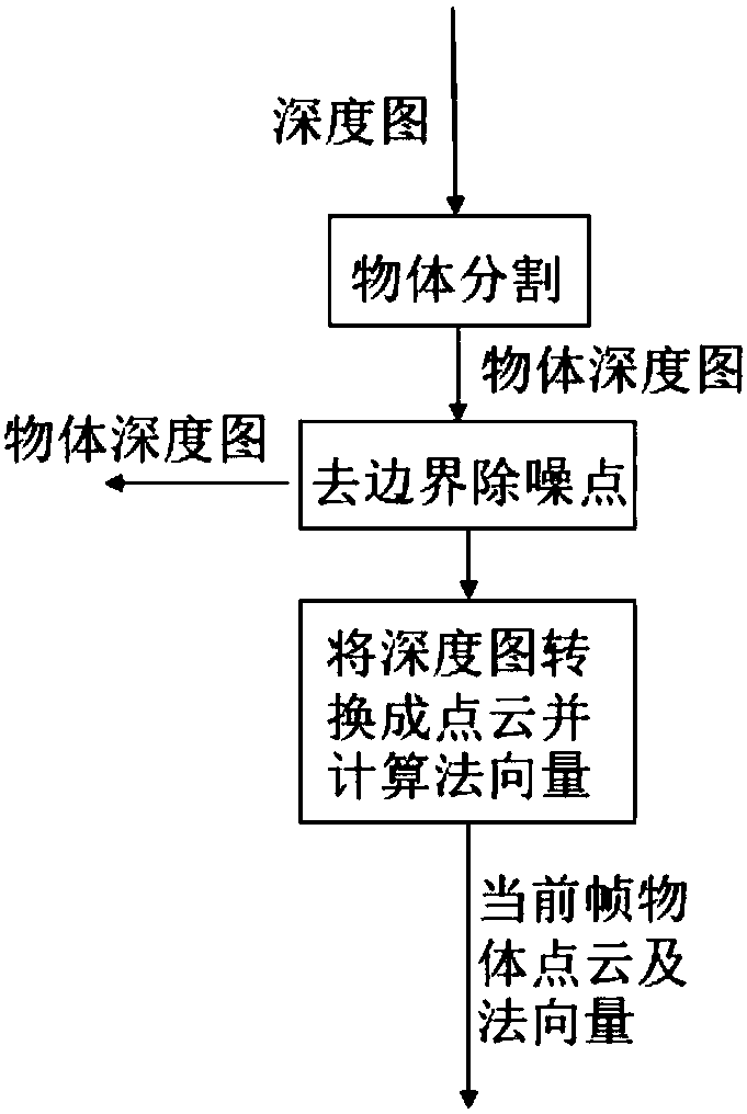
[0059] Step 1. Obtain the depth image from the depth camera, through the object segmentation in the preprocessing, remove the boundary and denoise points, generate the point cloud, and use PCA to calculate the point cloud normal vector to obtain the object depth image and object point cloud data after removing the boundary and denoising points and normal vectors.

[0060] Step 2. Use the centroids of the two frames of point clouds before and after to obtain the initial value of the camera translation, and then use the ICP algorithm to estimate the precise pose of the camera.

[0061] Step 3. Fuse the frame data into a local TSDF using the estimated precise camera pose.

[0062] Step 4. Determine whether there is an end instruction. The end instruction refers to the instruction issued when the program end instruction and the number of frames required for local TSDF fusion reach the predetermined...


PUM


Abstract

The invention provides a real-time object three-dimensional reconstruction method based on a depth camera. The method comprises the steps that a frame pf depth image is sequentially acquired from thedepth camera as a current frame and is preprocessed; the relative pose of the current frame and the previous frame is estimated through a centroid ICP algorithm, and the precise pose of the camera ofthe current frame is calculated by using the precise pose of the previous frame and the relative pose of the current frame and the previous frame; the current frame data are fused into the local TSDFby using the precise pose of the camera; and point cloud integrated into the local TSDF in the step 3 is acquired from the local TSDF, and the point cloud is used as the point cloud of the previous frame, or match fusion is carried out on the local TSDF and the global TSDF, and the local TSDF is initialized. According to the invention, the failure of the ICP matching algorithm is avoided; accumulated errors are reduced; the accuracy of a model is improved; and the method is suitable for reconstructing a specified object or person.

Description

technical field [0001] The invention relates to the field of three-dimensional imaging, in particular to a method capable of real-time three-dimensional reconstruction of objects or human bodies. Background technique [0002] 3D reconstruction technology has always been a hot topic in the field of computer graphics and computer vision. 3D reconstruction is to build a 3D model from the input data. With the emergence of various depth cameras for ordinary consumers, the technology of 3D scanning and reconstruction based on depth cameras has been developed rapidly. For points in the real scene, each frame of data scanned by the depth camera includes not only the color RGB image of the point in the scene, but also the distance value from each point to the vertical plane where the depth camera is located. This distance value becomes the depth value (depth), and these depth values ​​together form the depth image of this frame. [0003] The depth image can be regarded as a graysc...

Claims


Application Information

Patent Timeline
IPC IPC(8): G06T17/00G06T7/136G06T7/30G06T5/50
CPCG06T5/50G06T7/136G06T7/30G06T17/00G06T2207/10028G06T2207/20221
Inventor 曹彦鹏许宝杯曹衍龙杨将新何泽威付贵忠官大衍叶张昱董亚飞
Owner ZHEJIANG UNIV
Learn More