Bus spacer device not easy to slip and capable of being accurately adjusted

A spacer device, an uneasy technology, applied in the field of electric power, can solve problems such as the inability to achieve the spacer effect, the inability to realize multiple installations, and the inability to adjust the length, etc., and achieve the effects of quick and convenient adjustment, improved spacer efficiency, and reduced number of units used

Inactive Publication Date: 2018-03-23
张龙兵
View PDF0 Cites 0 Cited by
  • Summary
  • Abstract
  • Description
  • Claims
  • Application Information

AI Technical Summary

Problems solved by technology

In this process, busbars are needed, and the busbars need to be isolated during use. Now when installing and arranging the incoming busbars, busbar spacers are usually used to space the buses to be arranged. The existing busbars are spaced The device usually cannot adjust the corresponding length, and the busbar spacer can only be separated from one busbar, so it is impossible to realize multiple installations of one product
In addition, the position of the existing busbar spacer is easy to change, which cannot achieve a good spacing effect and requires repeated adjustments to adjust the space to a suitable position.

Method used


Image

  • Bus spacer device not easy to slip and capable of being accurately adjusted
  • Bus spacer device not easy to slip and capable of being accurately adjusted

Examples


Embodiment 1

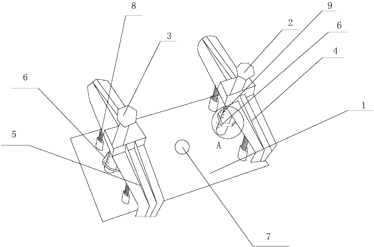
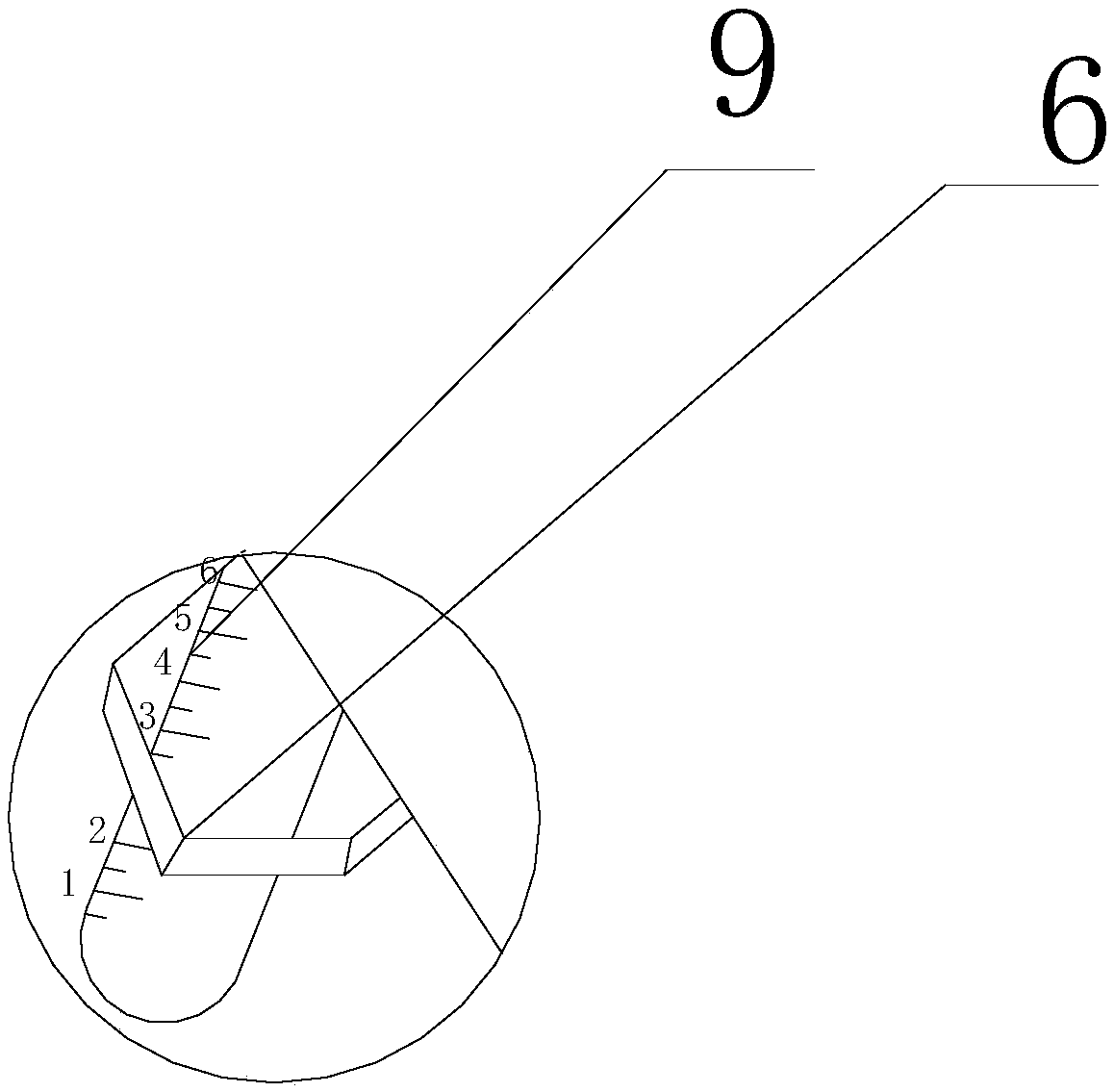
[0021] Such as Figure 1-2 As shown, this includes a busbar spacing device that is not easy to slip and can be accurately adjusted, including a base plate 1, a first installation column 2, a second installation column 3, a telescopic rod 8 and a scale line 9, the first installation column 2 and the second installation column The second mounting column 3 is vertically installed on the base plate 1, the first clamping plate 4 is set on the first mounting column 2, the first clamping plate 4 can move up and down on the first mounting column 2, and the second mounting column 3 is covered with The second clamping plate 5, the second clamping plate 5 can move up and down on the second mounting column 3, and both the first mounting column 2 and the second mounting column 3 are covered with limit nuts 6, and the limiting nuts 6 are located on the first clamping plate. The bottom of plate 4 and second clamping plate 5 is also provided with ventilation hole 7 on base plate 1; Also verti...

Embodiment 2

[0024] This embodiment is preferably as follows on the basis of the above embodiments: two telescopic rods 8 are provided at the bottoms of the first clamping plate 4 and the second clamping plate 5 . The two telescopic rods are fully able to support the first clamping board and the second clamping board well, so that the positions of the first clamping board and the second clamping board will not change.

[0025] The two telescopic rods 8 at the bottom of the first clamping plate 4 are symmetrical with respect to the first mounting column 2 . The stability of the first pallet and the second pallet is further improved.

[0026] The scale lines 9 form depressed horizontal stripes on the surfaces of the first mounting post 2 and the second mounting post 3 . The depressed horizontal stripes are used as scale lines, and are not easy to fall off during the long-term friction process between the first clamp and the second clamp.

[0027] A waterproof and scratch-resistant layer is...


PUM


Abstract

The invention discloses a bus bar spacing device which is easy to slide and can be precisely adjusted, comprising a bottom plate, a first installation column, a second installation column, a telescopic rod and a scale line, the first installation column and the second installation column are vertically installed on the bottom plate On the first mounting column, there is a first clamping plate, the first clamping plate can move up and down on the first mounting column, and the second mounting column is covered with a second clamping plate, the second clamping plate can be installed on the second mounting column. Move up and down on the column, set limit nuts on the first installation column and the second installation column, the limit nuts are located at the bottom of the first clamping plate and the second clamping plate; at the bottom of the first clamping plate and the second clamping plate A plurality of telescopic rods are vertically installed on the bottom plate; uniform scale marks are also arranged on the surfaces of the first mounting column and the second mounting column. Through the above-mentioned structure, the present invention can space multiple busbars at the same time, the risk of the first clamping plate and the second clamping plate falling downward is low, and the stability is greatly improved. In addition, the setting of the scale line has high adjustment accuracy.

Description

technical field [0001] The invention relates to the field of electric power, in particular to a bus bar spacing device which is not easy to slip and can be precisely adjusted. Background technique [0002] With the emergence of modern engineering facilities and equipment, the power consumption of all walks of life is increasing rapidly, especially the emergence of many high-rise buildings and large workshops. The traditional cables used as power transmission wires can no longer meet the requirements in large current transmission systems. The parallel use of multiple cables brings a lot of inconvenience to the site installation and construction connection. As a new type of power distribution wire, the plug-in busbar has emerged at the historic moment. Compared with the traditional cable, it fully demonstrates its superiority in the transmission of large currents. The contact resistance and temperature rise of the connection at both ends of the bus duct and the plug-in of the...

Claims


Application Information

Patent Timeline
Patent Type & Authority Applications(China)
IPC IPC(8): H02G5/02
CPCH02G5/02H02G5/025
Inventor 张龙兵
Owner 张龙兵
Why Eureka
Try Eureka