
Linkage method and linkage system of upper-level and lower-level fast switching devices

A fast switching and linkage system technology, applied in circuit devices, emergency protection circuit devices, information technology support systems, etc., can solve the problem of judging the slowness of fast switching devices, reduce the frequency of false actions, prevent false trips, and improve reliability sexual effect

Active Publication Date: 2020-09-01
CHINA PETROCHEMICAL CORP
View PDF6 Cites 0 Cited by
  • Summary
  • Abstract
  • Description
  • Claims
  • Application Information

AI Technical Summary

Problems solved by technology

As mentioned above, the current fast switching device itself does not judge whether the operation fails. The external equipment learns whether the fast switching device fails to operate, mainly through whether the backup power supply fails to close after the switching command of the fast switching device is issued. In this judgment, the specific closing method is not distinguished, so the process of judging whether the fast switching device fails to operate is relatively slow. If the upper-level fast switching device in the above-mentioned multi-level power supply and distribution network simply follows this judgment method, It judges that the action fails, and then notifies the lower-level quick switching device to start, but the lower-level quick switching device still cannot catch up with the backup power supply in the way of quick closing or synchronous catch closing

Method used


Image

  • Linkage method and linkage system of upper-level and lower-level fast switching devices
  • Linkage method and linkage system of upper-level and lower-level fast switching devices
  • Linkage method and linkage system of upper-level and lower-level fast switching devices

Examples


Embodiment 1

[0031] The linkage method of the upper and lower fast switching devices in Embodiment 1 includes the linkage method of the fast switching devices used for connecting the power supply and distribution system of each level to the backup power supply in the multi-level power supply and distribution network, wherein the adjacent upper and lower levels The fast switching device is hereinafter respectively referred to as an upper-level fast switching device and a lower-level fast switching device, and the linkage method includes the following steps:

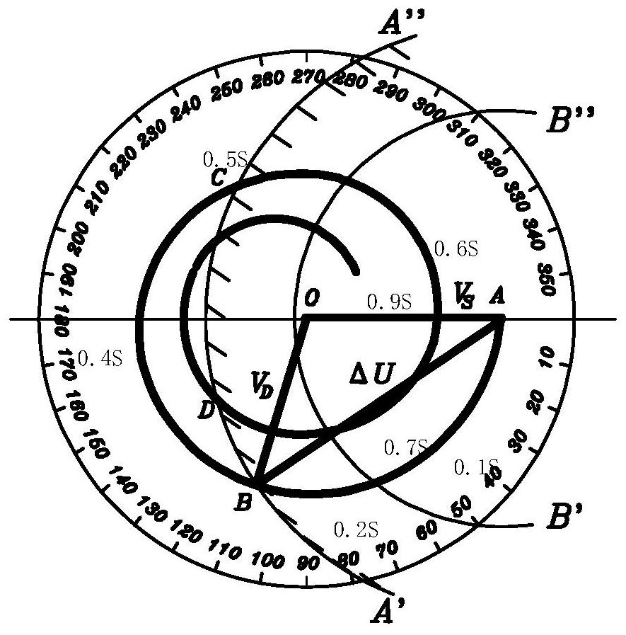
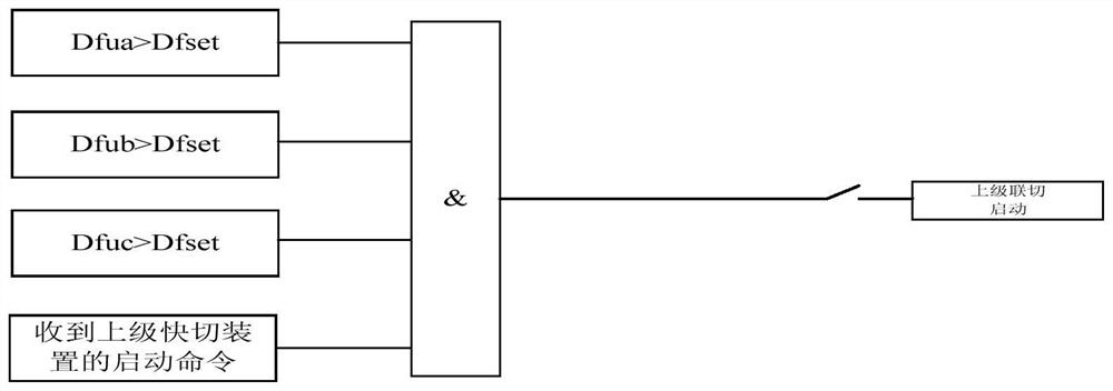
[0032] 1) If the action of the upper-level fast switching device fails, it will send a connection signal to the lower-level fast switching device; the logic of the upper-level fast switching device to judge its action failure is as follows: figure 1 Shown: the working power is disconnected, and the quick switching device starts switching, but the quick closing backup power fails; the working power and backup power here both refer to the...

Embodiment 2

[0037] The linkage method of the upper and lower fast switching devices of the second embodiment includes the linkage method of the fast switching devices used for connecting the power supply and distribution system of each level to the backup power supply in the multi-level power supply and distribution network, wherein the adjacent upper and lower levels The fast switching device is hereinafter respectively referred to as an upper-level fast switching device and a lower-level fast switching device, and the linkage method includes the following steps:

[0038] 1) If the action of the upper-level quick switching device fails, it will send a switching signal to the lower-level quick switching device; the logic for judging the action failure of the upper-level quick switching device is: the working power is disconnected, and the quick switching device starts switching, but the quick closing of the standby Power supply failure; the working power supply and backup power supply here...

Embodiment 3

[0043] The upper and lower level fast switching device linkage system of this implementation 3 includes a fast switching device for connecting each level of the power supply and distribution system to the backup power supply in the multi-level power supply and distribution network, wherein the adjacent upper and lower level fast switching devices are in the Hereinafter referred to as the upper-level fast switching device and the lower-level fast switching device respectively, the linkage system includes:

[0044] Action failure judging module: it is used by the superior fast switching device to judge whether its action fails. The judgment logic is: the working power is disconnected, and the fast switching device starts switching, but the fast closing backup power fails; here both the working power and the backup power refer to The working power supply and backup power supply controlled by the superior fast switching device;

[0045] The joint cut signal sending module is used ...


PUM


Abstract

The invention provides an upper and lower level quick switching device linkage method and linkage system. The linkage method comprises the steps of (1) sending an intertripping signal to a lower levelquick switching device if an upper level quick switching device fails to act, wherein the logic of judging an act failure by the upper level quick switching device is that a working power is disconnected, a quick switching device starts switching, and the quick switch-on of a backup power supply is failed, and (2) after the lower level quick switching device receives the shedding signal, startingthe lower level quick switching device immediately, switching off a controlled power supply, and then judging whether a condition is satisfied, emitting a switching operation command if so as to switching on a controlled backup power supply in a mode of quick switch-on or simultaneous capturing switch-on. According to the method, power supply can be quickly restored, and reliability of the powersupply of a multi-level power distribution network is improved.

Description

technical field [0001] The invention relates to a dual power supply fast switching device, in particular to the technical field of linkage between upper and lower level fast switching devices in a multi-level power supply and distribution network. Background technique [0002] The power supply mode of multi-level power supply and distribution network is generally as follows: power supply bureau --> main station --> substation --> substation. In order to improve the quality of power supply, each level of power supply and distribution system is connected to the backup power supply through a fast switching device. That is to say, each level of power supply and distribution system is actually equipped with two power supplies, one is the working power supply and the other is the backup power supply. [0003] The fast switching device is used to cut off the working power supply and switch on the standby power supply when the working power supply fails. The switching proc...

Claims


Application Information

Patent Timeline
Patent Type & Authority Patents(China)
IPC IPC(8): H02J9/06H02H7/26
CPCH02H7/262H02J9/061H02J9/068Y02B70/30Y04S20/20
Inventor 袁杰吴泳王子洋李宏湘邹国铖韦海波胡庭枝叶永荣钟兴
Owner CHINA PETROCHEMICAL CORP
Learn More