
Wireless charging dynamic control equipment and control method capable of supporting multiple loads

A wireless charging and dynamic control technology, applied in electric vehicles, arrangement of multiple synchronous batteries, current collectors, etc., can solve the problems of reduced system transmission efficiency, low system work efficiency, and high requirements, so as to improve the overall power transmission, improve Power transfer efficiency and strong architecture reusability

Pending Publication Date: 2018-03-23
BEIJING WINNER MICROELECTRONICS
View PDF2 Cites 15 Cited by
  • Summary
  • Abstract
  • Description
  • Claims
  • Application Information

AI Technical Summary

Problems solved by technology

The system adopting this arrangement will produce a large deviation in the coupling coefficient of the load coil at different positions, and a small movement of the load device may cause a large change in the received power, reduce the transmission efficiency of the system, and may even cause circuit damage. lead to safety hazards
[0006] Therefore, the existing wireless charging system has the following problems: high structural cost; poor reusability and flexibility; unreasonable distribution of transmission power, low system work efficiency, easy interruption of power transmission process, and poor product experience; The location of the equipment is highly required, and the location of the load equipment has a great influence on the transmission efficiency of the system

Method used


Image

  • Wireless charging dynamic control equipment and control method capable of supporting multiple loads
  • Wireless charging dynamic control equipment and control method capable of supporting multiple loads
  • Wireless charging dynamic control equipment and control method capable of supporting multiple loads

Examples


Embodiment Construction

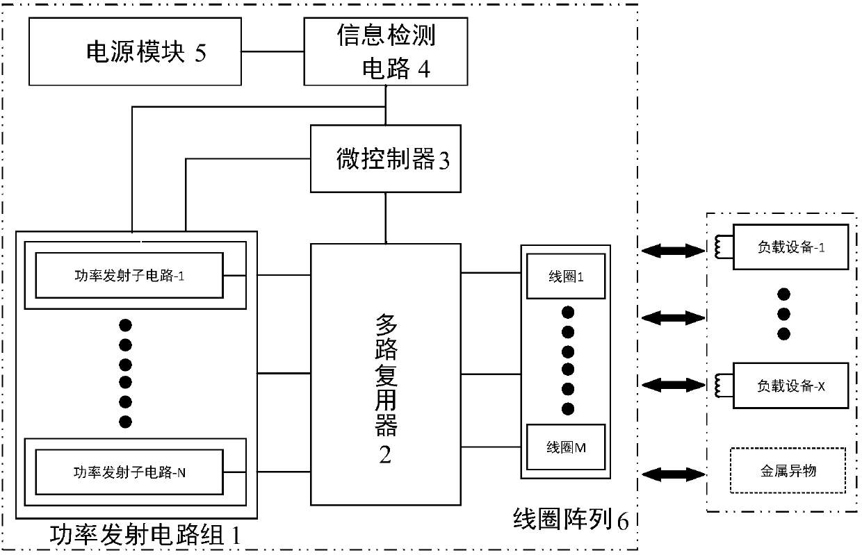
[0043] The present invention provides a wireless charging dynamic control device supporting multiple loads, such as figure 1 shown, where figure 1 The part in the dotted line box on the left is the main structure of the wireless charging dynamic control device, and the X load devices and metal foreign objects in the dotted line box on the right are loads for the entire system of the present invention, and the system can run without load , that is, X can be zero, that is, there must be no load device that needs power transmission, and figure 1 The load is drawn to indicate the relationship between the system and its load, and the possible content of the system load. The appearance of metal foreign objects will bring safety hazards, so it is a load that needs to be identified and eliminated during the operation of the system; load equipment Indicates the normal load of the system, which is the equipment for receiving power and charging.

[0044] The present invention provides ...


PUM


Abstract

The invention discloses wireless charging dynamic control equipment and control method capable of supporting multiple loads. The wireless charging dynamic control equipment comprises a power transmitting circuit group, a multiplexer, a micro controller, an information detection circuit, a power supply module and a coil array; the power supply module is connected with the information detection circuit; the information detection circuit is connected with the microcontroller and the power transmitting circuit group; the microcontroller is connected with the multiplexer and the power transmittingcircuit group; and one side of the multiplexer is connected with each sub circuit in the power transmitting circuit group while the other side is connected with each coil in the coil array. By virtueof the wireless charging dynamic control equipment, reasonable allocation of system resource can be realized, the system transmission efficiency can be improved, and product experience, safety and reliability can be improved; and by changing the coil array structure and parameters, the coupling coefficient deviation between the coil array and a load coil can be lowered.

Description

technical field [0001] The invention belongs to the technical field of wireless charging, and in particular relates to a wireless charging dynamic control device supporting multiple loads and a control method thereof. Background technique [0002] With the popularization of smart phones and wearable devices, the way of charging with power lines and data lines can no longer meet the explosive growth of smart devices. Wireless charging has developed rapidly in recent years, and wireless charging systems are more The ability to charge load devices has become the most urgent demand at present. For a wireless charging system, the transmission efficiency is the first indicator to measure the performance of the wireless charging system. It is necessary to effectively judge the power transmission requirements of the load device, reasonably allocate the power transmitted by the transmitting side to the load device, and build an efficient and reusable system architecture. It is the k...

Claims


Application Information

Patent Timeline
IPC IPC(8): H02J50/10H02J50/80H02J50/40H02J7/00H02J50/60
CPCH02J7/0026H02J7/0077H02J7/0088H02J7/025H02J7/0013H02J50/10H02J50/40H02J50/60H02J50/80
Inventor 张蕴千潘杰梅张雄
Owner BEIJING WINNER MICROELECTRONICS
Learn More