Motor stator and motor with same

A technology for motor stators and sub-stators, which is applied to electrical components, electromechanical devices, electric components, etc., can solve the problems of limiting the production efficiency of motor stators, easy axial dislocation of stator iron cores, and difficult assembly operations, and achieves guaranteed performance. , The effect of saving materials and convenient assembly

Pending Publication Date: 2018-03-23
GUANGDONG WELLING ELECTRIC MACHINE MFG +1
View PDF4 Cites 1 Cited by
  • Summary
  • Abstract
  • Description
  • Claims
  • Application Information

AI Technical Summary

Problems solved by technology

However, in this way, the assembly operation between the multiple modules of the stator yoke is relatively difficult, and usually needs to be completed with the help of other tools, thus limiting the production efficiency of the motor stator
In addition, when the motor stator is installed on the motor casing, the segmented stator core is prone to axial misalignment and other problems

Method used


Image

  • Motor stator and motor with same
  • Motor stator and motor with same
  • Motor stator and motor with same

Examples


Embodiment 1

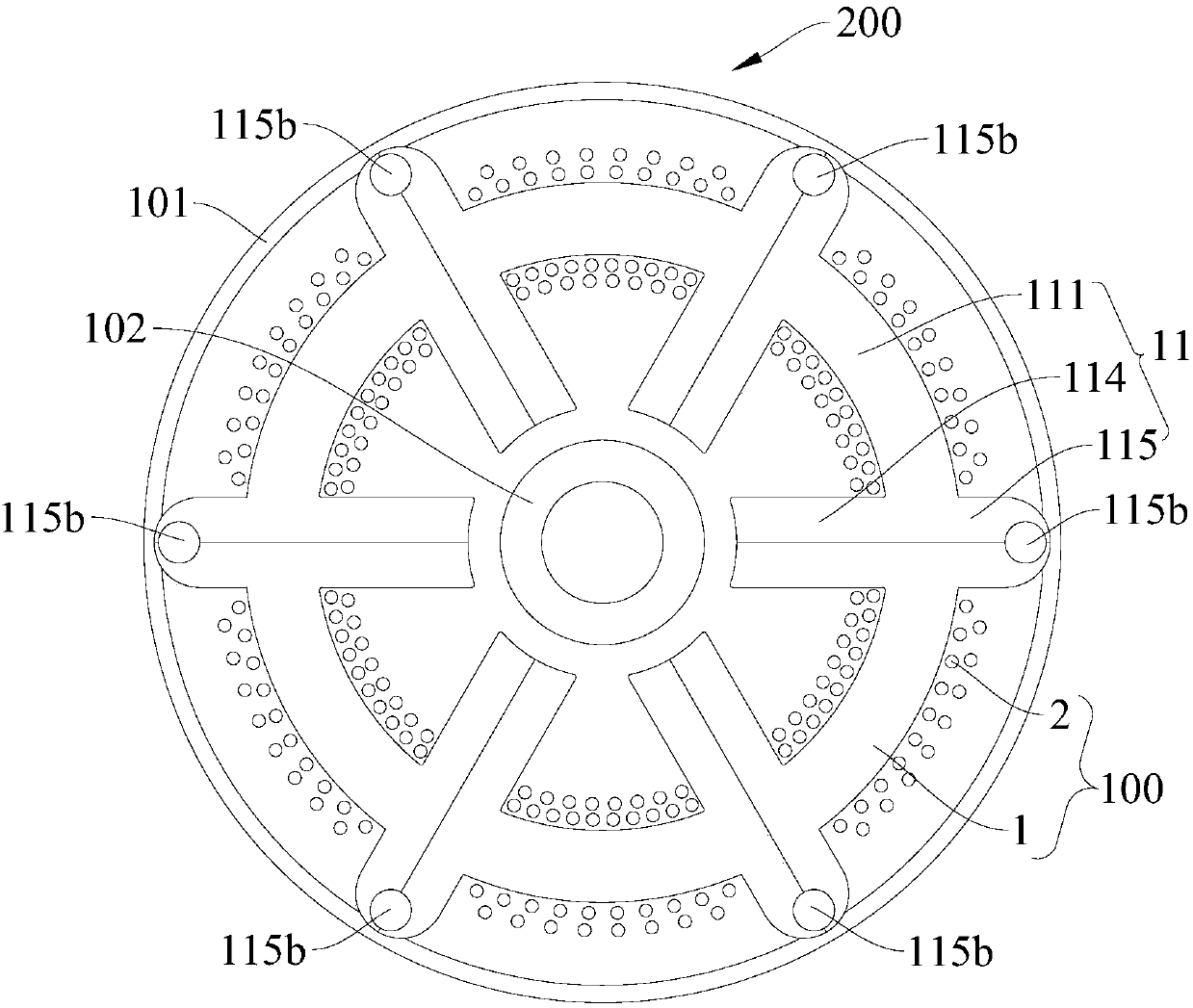
[0071] In this example, if figure 1 As shown, the motor 200 includes a casing 101, a motor stator 100 and a motor rotor 102, the casing 101 is roughly a cylindrical structure, six recesses 101a are formed on the inner wall of the casing 101, and the motor stator 100 is formed with six recesses 101a corresponds to the matching convex surface one by one, the motor rotor 102 is coaxially embedded in the motor stator 100, and the motor rotor 102 is a two-stage permanent magnet ring integrally formed.

[0072] The motor stator 100 includes a stator core and six stator windings 2. The stator core includes six stator cores 11 connected end to end along the circumferential direction. The six stator cores 11 have the same structure and each stator core 11 is composed of A plurality of punched sheets are stacked, and each stator core 11 includes a stator yoke 111, two stator teeth 114 and two connecting outer ends 115, and the stator teeth of two adjacent stator cores 11 are in contact ...

Embodiment 2

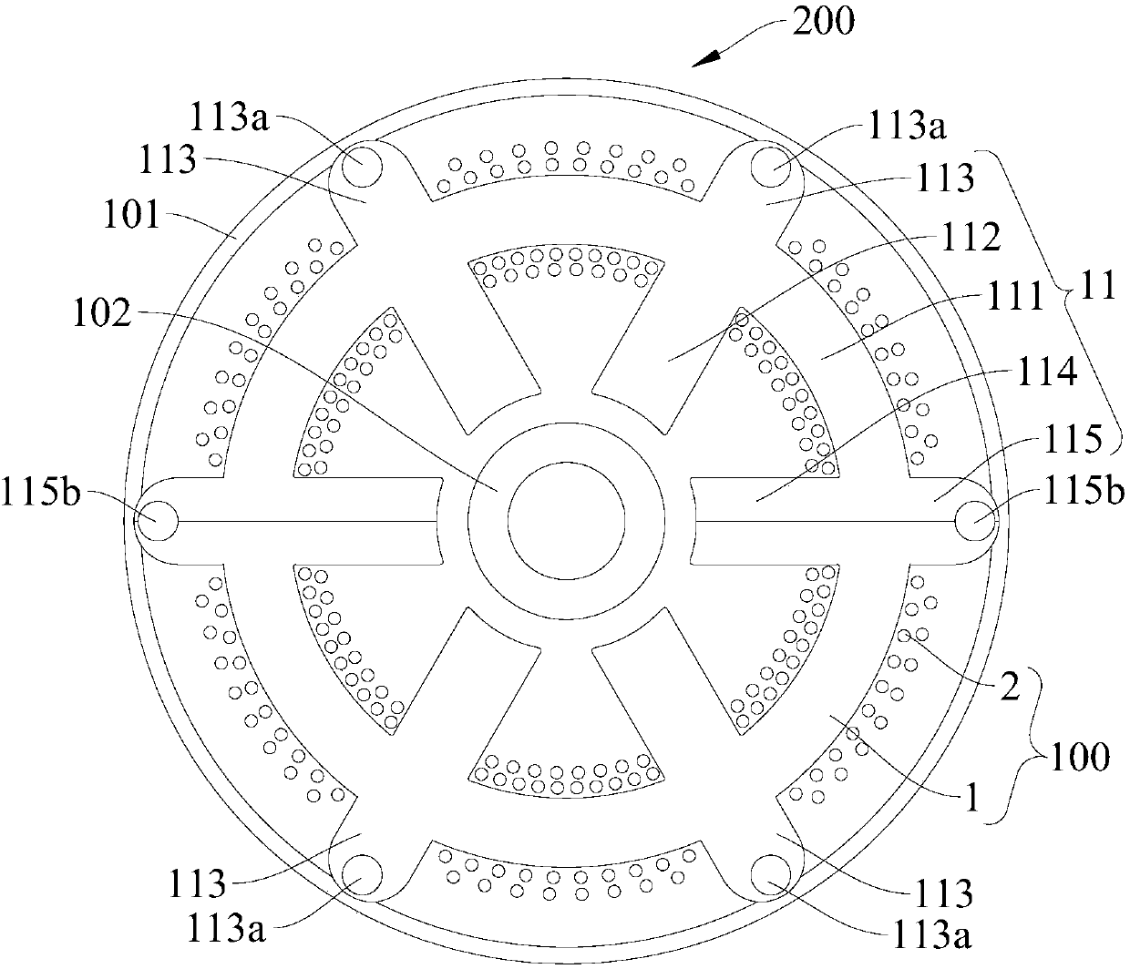
[0077] like figure 2 As shown, the structure of this embodiment is substantially the same as that of Embodiment 1, wherein the same components use the same reference numerals, and the difference is that the stator core includes two sub-stator cores 11 connected end-to-end along the circumferential direction, Each stator core 11 includes a stator yoke 111, two stator teeth 114, two stator teeth 112, two outer ends 113 and two connecting outer ends 115, the stator teeth 112 are connected with the complete stator teeth The structure is the same, the two stator teeth 112 are arranged on the inner side of the stator yoke 111 and in the circumferential direction of the stator yoke 111, the two stator teeth 112 are evenly spaced between the two stator teeth 114, and the two outer ends The part 113 is arranged on the outer side of the stator yoke part 111, and the two outer ends 113 are arranged radially opposite to the two stator tooth parts 112 respectively; each outer end part 113...

Embodiment 3

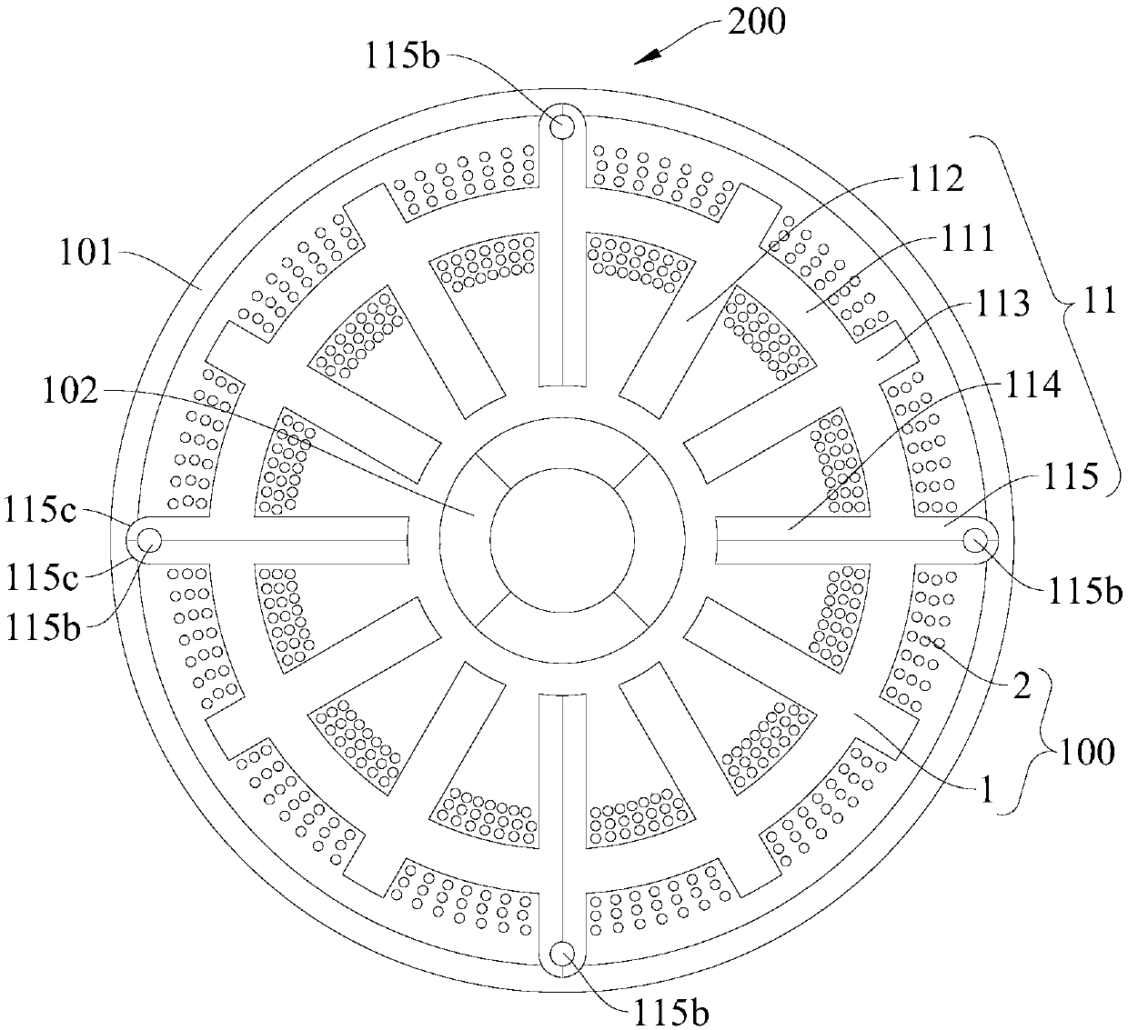
[0079] like Figure 3-Figure 6 As shown, the structure of this embodiment is substantially the same as that of Embodiment 2, wherein the same components use the same reference numerals, the difference is that: the motor rotor 102 is a four-stage permanent magnet ring; the inner wall of the casing 101 is formed with Four recesses 101a; the stator core includes four sub-stator cores 11 connected end-to-end along the circumferential direction, and each sub-stator core 11 includes a stator yoke 111, two sub-stator teeth 114, two stator teeth 112, Two outer ends 113 and two connecting outer ends 115, the stator teeth 112 have the same structure as the complete stator teeth; each outer end 113 is not formed with a positioning installation hole 113a, and the length of the outer ends 113 Less than the length of the connecting outer end 115, at this time the four concave and convex surfaces match.


PUM


Abstract

The invention discloses a motor stator and a motor with the motor stator. The motor stator comprises a stator core and a stator winding, wherein the stator core comprises a plurality of sub stator cores; each sub stator core comprises a stator yoke part, two sub stator tooth parts and two connecting outer end parts; the stator winding is wound on the stator yoke parts; the two sub stator tooth parts are arranged on the inner side of the corresponding stator yoke part respectively and are positioned at two ends of the corresponding stator yoke part in the peripheral direction respectively; thetwo connecting outer end parts are arranged on the outer side of the corresponding stator yoke part respectively and are opposite to the two corresponding sub stator tooth parts respectively; a grooveis formed in each connecting outer end part; two grooves of the connecting outer end parts in contact with the two adjacent sub stator cores form a mounting hole; and each mounting groove is internally matched with a connecting piece so as to realize connection and mounting positioning of every two adjacent sub stator cores. According to the motor stator disclosed by the invention, the motor stator is convenient to manufacture, small in assembling difficulty and high in production efficiency, and axial positioning between every two adjacent sub stator cores is easily guaranteed.

Description

technical field [0001] The invention relates to the technical field of motor manufacturing, in particular to a motor stator and a motor having the same. Background technique [0002] In the related art, most of the stator cores of the motor adopt an integrated structure, which makes it inconvenient to wind the wire on the stator yoke, which leads to inconvenient and low processing efficiency of the motor stator. In order to simplify the production process of the motor stator, in some technologies, during the production of the motor stator, the stator yoke, the stator teeth and the stator winding are respectively modularized, and then these modules are assembled into a complete motor stator. However, in this way, the assembly operation between the multiple modules of the stator yoke is relatively difficult, and usually needs to be completed with other tools, thereby limiting the production efficiency of the motor stator. In addition, when the motor stator is installed on the...

Claims


Application Information

Patent Timeline
Patent Type & Authority Applications(China)
IPC IPC(8): H02K1/14H02K5/04
CPCH02K1/146H02K5/04H02K2201/09
Inventor 武谷雨吴迪陈金涛
Owner GUANGDONG WELLING ELECTRIC MACHINE MFG
Why Eureka
Try Eureka