High-boost-capacity type Z-source inverter topological structure

A source inverter and topology technology, applied in the field of high boost capability Z-source inverter topology, can solve the problems of narrow input voltage application range and weak boost capability, so as to increase the applicable range and improve boost. pressure capacity, highlight the effect of substantive characteristics

Inactive Publication Date: 2018-03-23
QILU UNIV OF TECH
View PDF2 Cites 5 Cited by
  • Summary
  • Abstract
  • Description
  • Claims
  • Application Information

AI Technical Summary

Problems solved by technology

However, the existing Z-source inverter has a relatively weak boost capability.
Although there are many improvements to the existing Z-source inverter in the prior art, the existing Z-source inverter still has the problems of weak boosting capability and relatively narrow application range of input voltage.

Method used


Image

  • High-boost-capacity type Z-source inverter topological structure
  • High-boost-capacity type Z-source inverter topological structure
  • High-boost-capacity type Z-source inverter topological structure

Examples


specific Embodiment approach 1

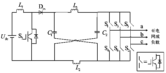
[0024] Such as figure 1 As shown, a high boost capability Z-source inverter topology of the present invention includes a DC power supply U dc , the DC power supply U dc The positive pole and the seventh inductance L 7 The first end is connected, the seventh inductance L 7 The second terminals of the diodes D in The anode of and the seventh switching tube S 7 connected to the first end of the diode D in The cathodes are respectively connected with the first capacitor C 1 positive pole and the fifth inductor L 5 connected to the first terminal, the fifth inductance L 5 The second end of the second capacitor and the second capacitor C 2 positive pole of the first switch tube S 1 The first terminal of the third switch tube S 3 The first terminal and the fifth switch tube S 5 connected to the first end; the first switching tube S 1 The second end of the inverter is respectively connected with the first output port a of the inverter and the fourth switch tube S 4 connec...

specific Embodiment approach 2

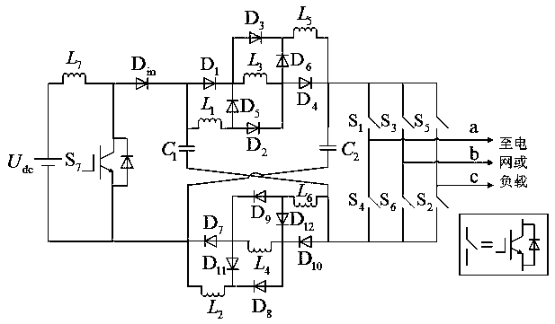
[0026] Such as figure 2 As shown, a high boost capability Z-source inverter topology of the present invention includes a DC power supply U dc , the DC power supply U dc The positive pole and the seventh inductance L 7 The first end is connected, the seventh inductance L 7 The second terminals of the diodes D in The anode of and the seventh switching tube S 7 connected to the first end of the diode D in The cathodes are respectively connected with the first capacitor C 1 positive pole, the first inductance L 1 The first terminal and the first diode D 1 connected to the anode of the first diode D 1 The cathodes are respectively connected with the third diode D 3 The anode of the third inductance L 3 The first terminal and the fifth diode D 5 connected to the cathode of the fifth diode D 5 The anodes of the second diode D are respectively connected to the 2 The anode and the first inductor L 1 The second terminal is connected; the second diode D 2 The cathodes are...


PUM


Abstract

The invention provides a high-boost-capacity type Z-source inverter topological structure. A switch tube S7 and an inductor L7 are arranged at the front stage of a Z-source network, and the switch tube S7 and the inductor L7 are combined with an input diode Din. The high-boost-capacity Z-source inverter topological structure further comprises six inductors L1-L6 with the same inductance values, two capacitors C1 and C2 with the same capacitance values, and twelve identical diodes, wherein the L1, L3 and L5, and the D1-D6 form an upper switch inductance unit, the L2, L4 and L6, and D7-D12 forma lower switch inductance unit. The boosting capacity of the Z-source inverter is improved, and the application range of the Z-source inverter on the input voltage is also expanded.

Description

technical field [0001] The invention relates to the field of Z-source inverters, in particular to a topological structure of a Z-source inverter with high boosting capability. Background technique [0002] At present, power electronic power conversion technology is widely used in renewable energy generation, and the inverter is an indispensable power electronic power converter. Practice has shown that the performance of the inverter directly determines the quality of power generated by renewable energy. [0003] However, in the field of renewable energy power generation, the input voltage usually changes in a wide range. When the input voltage is low, if the inverter is to maintain a normal output voltage amplitude, it needs to have a strong boost capability. However, the boosting capability of the existing Z-source inverter is relatively weak. Although many improvements have been made to the existing Z-source inverter in the prior art, the existing Z-source inverter still...

Claims


Application Information

Patent Timeline
Patent Type & Authority Applications(China)
IPC IPC(8): H02M7/48
CPCH02M7/48
Inventor 张迎春李长云张超
Owner QILU UNIV OF TECH
Why Eureka
Try Eureka