High-gain bridgeless PFC (Power Factor Correction) convertor based on coupling inductor voltage-multiplying unit

A coupled inductor, high-gain technology, applied in the field of AC/DC conversion, to achieve high efficiency, simple circuit structure, and boost boost effect

Pending Publication Date: 2017-06-13
NANJING UNIV OF AERONAUTICS & ASTRONAUTICS
View PDF5 Cites 2 Cited by
  • Summary
  • Abstract
  • Description
  • Claims
  • Application Information

AI Technical Summary

Problems solved by technology

[0004] In order to solve the technical problems raised by the above-mentioned background technology, the present invention aims to provide a high-gain bridgeless PFC converter based on a coupled inductor voltage doubler unit to solve the problems encountered in the application of traditional bridgeless PFC converters in high-gain applications

Method used


Image

  • High-gain bridgeless PFC (Power Factor Correction) convertor based on coupling inductor voltage-multiplying unit
  • High-gain bridgeless PFC (Power Factor Correction) convertor based on coupling inductor voltage-multiplying unit
  • High-gain bridgeless PFC (Power Factor Correction) convertor based on coupling inductor voltage-multiplying unit

Examples


Embodiment Construction

[0025] The technical solutions of the present invention will be described in detail below in conjunction with the accompanying drawings.

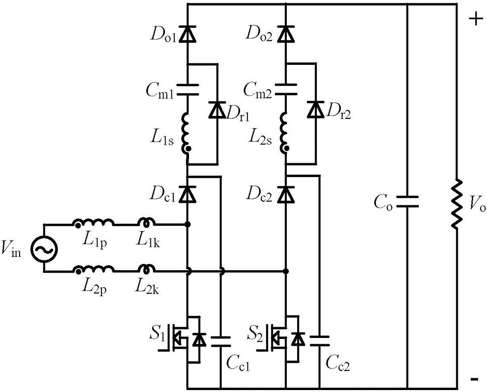
[0026] Such as figure 1 As shown, the high-gain bridgeless PFC converter based on the coupled inductor voltage doubler unit includes the first coupled inductor, the second coupled inductor, the first main power switch S 1 , the second main power switch tube S 2 , the first output diode D o1 , the second output diode D o2 , the first clamping diode D c1 , the second clamping diode D c2 , the first clamp capacitor C c1 , the second clamp capacitor C c2 , the first freewheeling diode D r1 , the second freewheeling diode D r2 , the first voltage doubler capacitor C m1 , the second voltage doubler capacitor C m2 and the output capacitor C o . The first coupled inductor consists of the first winding L 1p and the second winding L 1s , the second coupled inductor consists of the first winding L 2p and the second winding L 2s . The ...


PUM


Abstract

The invention discloses a high-gain bridgeless PFC (Power Factor Correction) convertor based on a coupling inductor voltage-multiplying unit. The high-gain bridgeless PFC convertor based on the coupling inductor voltage-multiplying unit comprises a first coupling inductor, a second coupling inductor, a first main power switching tube, a second main power switching tube, a first output diode, a second output diode, a first clamping diode, a second clamping diode, a first clamping capacitor, a second clamping capacitor, a first freewheel diode, a second freewheel diode, a first voltage-multiplying capacitor, a second voltage-multiplying capacitor and an output capacitor; the first coupling inductor comprises a first winding and a second winding; the second coupling inductor comprises a first winding and a second winding. According to the high-gain bridgeless PFC convertor based on the coupling inductor voltage-multiplying unit, the original inductor is replaced by using the coupling inductor voltage-multiplying unit on the basis of the conventional bridgeless PFC converter topology; high gain is realized through the coupling inductor voltage-multiplying unit; a circuit is prevented from working in an ultimate duty ratio state; the high-gain bridgeless PFC convertor based on the coupling inductor voltage-multiplying unit is suitable for the place which requires the power factor correction and is high in gain.

Description

technical field [0001] The invention belongs to the field of AC / DC conversion, and relates to a bridgeless PFC converter, in particular to a high-gain bridgeless PFC converter. Background technique [0002] With the global environmental pollution and energy crisis, renewable energy such as solar energy, wind energy, ocean energy, etc. has attracted more and more attention from all over the world. As a form of marine energy, wave energy is of great significance to rationally and effectively utilizing wave energy to solve the energy crisis and protect the environment. Magnetic fluid generators can effectively use wave energy and convert it into electrical energy. However, the power factor of the output power of magnetic fluid generators is low, the cycle is long, and its output voltage is low and the output current is large. In practical applications, a A high-gain converter performs step-up and power factor correction on it. [0003] The traditional bridgeless PFC converter...

Claims


Application Information

Patent Timeline
Patent Type & Authority Applications(China)
IPC IPC(8): H02M7/04H02M7/217H02M1/42
CPCH02M1/4225H02M7/043H02M7/217Y02B70/10Y02P80/10
Inventor 程朵朵王慧贞徐智成张红岩施艳萍
Owner NANJING UNIV OF AERONAUTICS & ASTRONAUTICS
Why Eureka
Try Eureka