Novel punching machine

A stamping machine, a new type of technology, applied in the field of stamping machines, can solve problems such as the inability to collect waste materials centrally, hinder equipment operation, and complex stamping structures, and achieve the effects of facilitating secondary processing, protecting the machine body, and saving resources

Inactive Publication Date: 2018-03-27
苏州特精模具有限公司
View PDF0 Cites 7 Cited by
  • Summary
  • Abstract
  • Description
  • Claims
  • Application Information

AI Technical Summary

Problems solved by technology

[0003] When the existing stamping machine is being processed, due to the complex stamping structure, parts are prone to damage due to poor shock absorption during the impact process. The situation that hinders the operation of the equipment is caused, and the waste cannot be collected centrally, wasting resources

Method used


Image

  • Novel punching machine
  • Novel punching machine
  • Novel punching machine

Examples


Embodiment 1

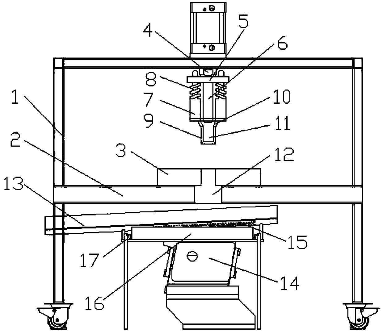
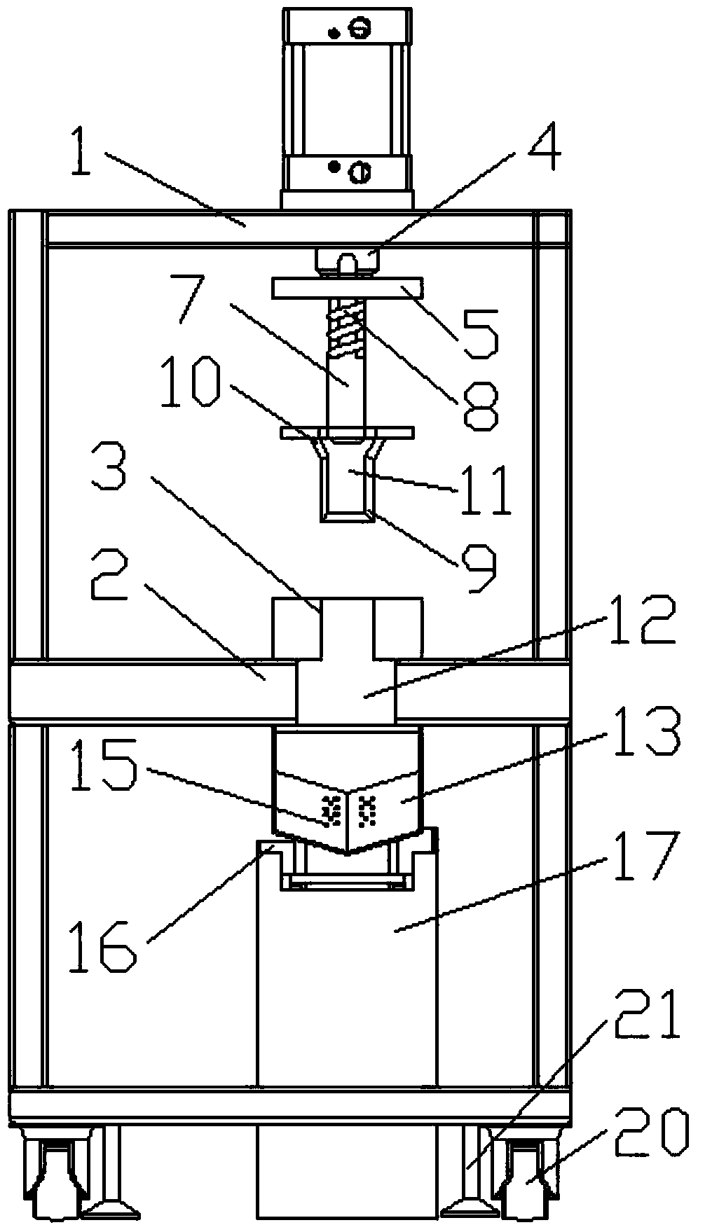
[0025] Such as figure 1 As shown, a new type of punching machine includes a frame 1, a working platform 2 is provided below the frame 1, and a punching rod 4 is provided above the frame 1, and the punching rod 4 is opposite to the working platform 2 A stamping plate 5 is provided at the end of the stamping plate 5, a fixed rod 6 is connected below the stamping plate 5, guide arms 7 are provided on both sides of the fixed rod 6, and the stamping plate 5 on both sides of the fixed rod 6 is provided with working holes , The upper end of the guide arm 7 passes through the working hole on the punching plate 5, the upper end of the guide arm 7 is provided with a limit part, and the guide arm 7 is located outside the lower part of the punching plate 5. Damping spring 8, the lower end of the guide arm 7 is connected with a punching tool 9, a funnel-shaped connecting tube 10 is also provided between the punching tool 9 and the guide arm 7, and a cavity 11 is provided in the punching tool...

Embodiment 2

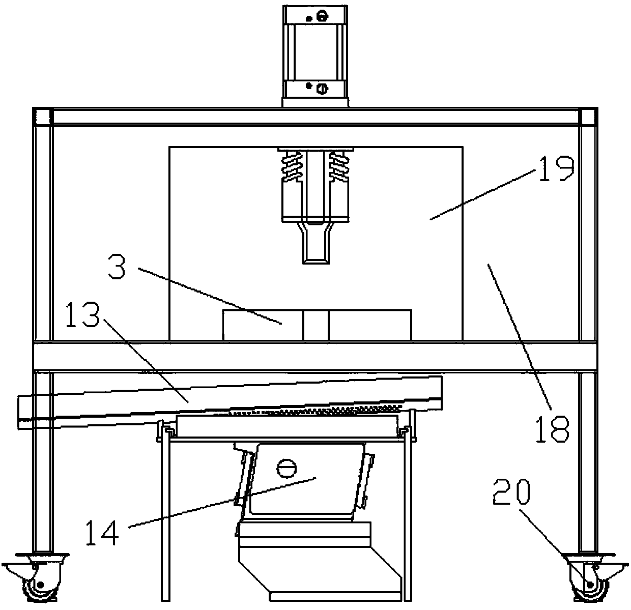
[0028] Such as image 3 As shown, on the basis of the first embodiment, in order to protect the safety of the operator, a safety baffle 18 is provided on the periphery of the rack 1, and a transparent observation window 19 is provided on the safety baffle 18. 18 can protect the operator from being scratched by the processing flying debris. At the same time, the transparent observation window 19 is convenient for observing the internal processing conditions. In order to facilitate the movement of the punching machine, the bottom four corners of the frame 1 are provided with stopperable casters 20. To further stabilize the press, an adjusting foot 21 is provided beside the caster 20, and a tapered anti-skid pad is provided at the lower end of the adjusting foot 21.


PUM


Abstract

The invention discloses a novel stamping machine, which comprises a frame, a working platform is arranged under the frame, a punching rod is arranged above the frame, a punching plate is arranged at the end of the punching rod opposite to the working platform, and a fixing plate is connected under the punching plate. There is a guide arm on both sides of the fixed rod, and a damping spring is provided on the outside of the guide arm. The lower end of the guide arm is connected to the stamping tool. There is a cavity inside the stamping tool. There is a waste sorting device in the frame below the processing through hole. The waste sorting device includes a material distribution trough and a vibrator located below the material distribution trough. There is a collection box, and the shock-absorbing spring can effectively buffer the impact of the stamping tool on the body to protect the body. At the same time, the fixed rod pushes the residual waste in the cavity out of the cavity, and the waste is cleaned thoroughly. The waste material is separated from the metal chips, which is convenient for secondary processing.

Description

Technical field [0001] The invention relates to the technical field of punching machines, in particular to a new type of punching machine. Background technique [0002] Stamping machine is abbreviated as stamping machine, also known as press, which is equipment used for pressure processing of materials. Its working principle is generally through the opening and closing of the upper mold and the lower mold driven by the machine tool under the action of the punching power, and the raw materials between them are cut, punched, stretched, etc. to form the stamping parts. According to the working principle of the press, it can be divided into mechanical press and hydraulic press. The mechanical press completes the stamping process through the movement of the sliding block driven by the motor; the hydraulic press drives the hydraulic steel to reciprocate through the hydraulic principle to complete the stamping process. The mechanical press has a fast reciprocating frequency, high spee...

Claims


Application Information

Patent Timeline
Patent Type & Authority Applications(China)
IPC IPC(8): B21D28/02B21D55/00B21D43/20B03C1/02
CPCB21D28/02B03C1/02B21D43/20B21D55/00
Inventor 付朝黄荣利郭宁州
Owner 苏州特精模具有限公司
Why Eureka
Try Eureka