Rapid shunt winding device for copper wire of power line

A power cord and copper wire technology, applied in the field of power cord copper wire rapid winding device, can solve the problems of slow production, low efficiency and high labor cost

Inactive Publication Date: 2018-03-27
刘同海
View PDF7 Cites 8 Cited by
  • Summary
  • Abstract
  • Description
  • Claims
  • Application Information

AI Technical Summary

Problems solved by technology

[0006] In order to overcome the existing copper wire coiling production, the present invention is generally carried out manually, which has the disadvantages of slow production, high labor cost and low efficiency. The technical problem to be solved by the present invention is to provide a fast production, high efficiency and Power cord copper wire decoiling device with low labor cost

Method used


Image

  • Rapid shunt winding device for copper wire of power line
  • Rapid shunt winding device for copper wire of power line
  • Rapid shunt winding device for copper wire of power line

Examples


Embodiment 1

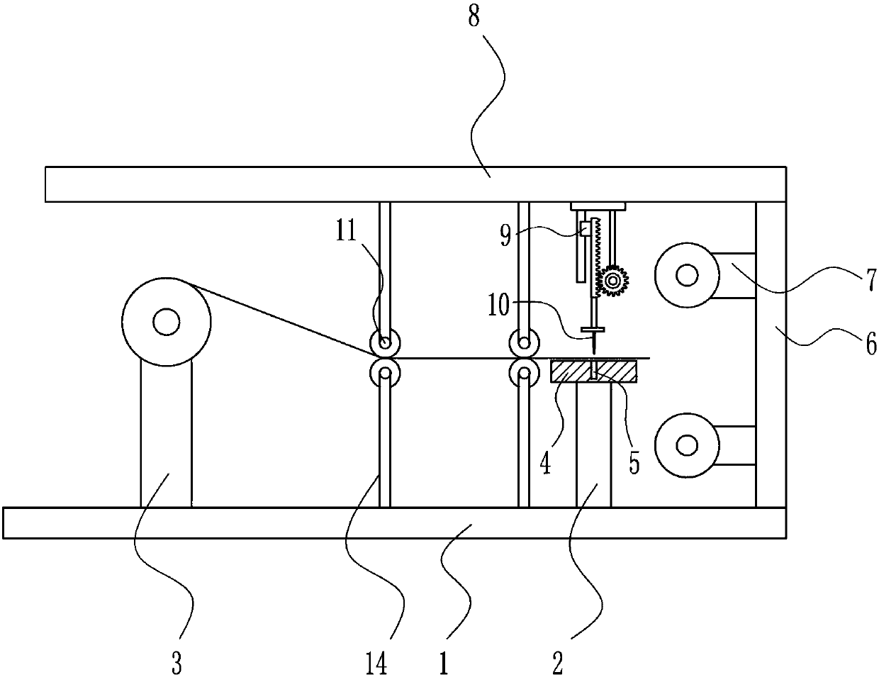
[0028] A power cord copper wire fast winding device, such as Figure 1-5 As shown, it includes a bottom plate 1, a support seat 2, a wire feeding mechanism 3, a cutting table 4, a side plate 6, a winding mechanism 7, a top plate 8, a lifting mechanism 9, a cutting blade 10, a roller 11 and a pole 14; The wire mechanism 3, the support seat 2 and the side plate 6 are sequentially fixed on the top of the bottom plate 1; the cutting table 4 is fixed on the top of the support seat 2, and the cutting table 4 is provided with a cutting groove 5; the winding mechanism 7 is fixed on the side plate 6 is close to the side of the support seat 2, the top plate 8 is fixed on the top of the side plate 6; the lifting mechanism 9 is fixed on the bottom of the top plate 8, and the cut is located directly above the cutting table 4; the cutting blade 10 is fixed on the output end of the lifting mechanism 9 , and located directly above the cutting groove 5; the four rollers 11 are symmetrically fi...

Embodiment 2

[0030] A power cord copper wire fast winding device, such as Figure 1-5 As shown, it includes a bottom plate 1, a support seat 2, a wire feeding mechanism 3, a cutting table 4, a side plate 6, a winding mechanism 7, a top plate 8, a lifting mechanism 9, a cutting blade 10, a roller 11 and a pole 14; The wire mechanism 3, the support seat 2 and the side plate 6 are sequentially fixed on the top of the bottom plate 1; the cutting table 4 is fixed on the top of the support seat 2, and the cutting table 4 is provided with a cutting groove 5; the winding mechanism 7 is fixed on the side plate 6 is close to the side of the support seat 2, the top plate 8 is fixed on the top of the side plate 6; the lifting mechanism 9 is fixed on the bottom of the top plate 8, and the cut is located directly above the cutting table 4; the cutting blade 10 is fixed on the output end of the lifting mechanism 9 , and located directly above the cutting groove 5; the four rollers 11 are symmetrically fixe...

Embodiment 3

[0033] A power cord copper wire fast winding device, such as Figure 1-5 As shown, it includes a bottom plate 1, a support seat 2, a wire feeding mechanism 3, a cutting table 4, a side plate 6, a winding mechanism 7, a top plate 8, a lifting mechanism 9, a cutting blade 10, a roller 11 and a pole 14; The wire mechanism 3, the support seat 2 and the side plate 6 are sequentially fixed on the top of the bottom plate 1; the cutting table 4 is fixed on the top of the support seat 2, and the cutting table 4 is provided with a cutting groove 5; the winding mechanism 7 is fixed on the side plate 6 is close to the side of the support seat 2, the top plate 8 is fixed on the top of the side plate 6; the lifting mechanism 9 is fixed on the bottom of the top plate 8, and the cut is located directly above the cutting table 4; the cutting blade 10 is fixed on the output end of the lifting mechanism 9 , and located directly above the cutting groove 5; the four rollers 11 are symmetrically fi...


PUM


Abstract

The invention relates to shunt winding devices, in particular to a rapid shunt winding device for a copper wire of a power line. According to the rapid shunt winding device for the copper wire of thepower line, production is fast, the efficiency is high, and the labor cost is low. The rapid shunt winding device for the copper wire of the power line comprises a bottom plate, a supporting seat, a wire feeding mechanism, a cutting table, a side plate, wire winding mechanisms, a top plate and the like. A cutting groove is formed in the cutting table; the wire winding mechanisms are fixedly connected to the side part, close to the supporting seat, of the side plate; the top plate is fixedly connected to the top of the side plate; a lifting mechanism is fixedly connected to the bottom of the top plate and located over the cutting table; and a cutting blade is fixedly connected to the output end of the lifting mechanism. Through matching of the wire feeding mechanism, the wire winding mechanisms and the lifting mechanism, the rapid shunt winding effect is achieved; and by applying the rapid shunt winding device, the production rate is guaranteed, the labor cost is reduced, and the production quality is further improved.

Description

technical field [0001] The invention relates to a coiling device, in particular to a rapid coiling device for copper wire of a power cord. Background technique [0002] Power cords are wires that carry electricity. Usually the way of current transmission is point-to-point transmission. Power cords can be divided into AC power cords and DC power cords according to their uses. Usually, AC power cords are wires that pass through high-voltage alternating current. Due to the high voltage, such wires require uniform standards to obtain safety certification before they can be formally produced. The DC line basically passes DC with a lower voltage, so the safety requirements are not as strict as the AC line, but for safety reasons, countries still require unified safety certification. [0003] Copper wire refers to the wire drawn from hot-rolled copper rods without annealing (but smaller wires may require intermediate annealing), which can be used for weaving nets, cables, copper ...

Claims


Application Information

Patent Timeline
Patent Type & Authority Applications(China)
IPC IPC(8): B21F11/00B21F23/00
Inventor 刘同海
Owner 刘同海
Why Eureka
Try Eureka