Packaging box and manufacturing process thereof

A production process and packaging box technology, applied in the field of packaging boxes, can solve the problems of not being able to keep up with the growth rate, consume manpower and material resources, and difficult processing methods, and achieve the effects of convenient and fast packaging, environmental protection, and novel overall structure design

Inactive Publication Date: 2018-03-27
HANGZHOU YONGHUA PRINTING & PACKING CO LTD
View PDF10 Cites 9 Cited by
  • Summary
  • Abstract
  • Description
  • Claims
  • Application Information

AI Technical Summary

Problems solved by technology

[0005] This kind of packaging box, in actual use, only needs to tear off the covering strip on the double-sided adhesive tape by hand, and glue the sealing plate and the front wall of the box body through double-sided adhesive tape to realize the sealing work of the box body. When packaging, hold the end of the tear strip and tear the sawtooth tear strip outwards forcefully. The serrated tear strip is separated from the sealing plate, and the sealing plate is divided into upper and lower parts. The upper part is connected with the box cover, and the lower part is adhered to the front of the box body. The wallboard can realize fast assembly and easy opening of the packaging box, which brings great convenience to people's life, but in actual production and processing, most of the finished double-sided adhesive tapes produced need to tear off the covering strip on one side before passing through. Manually stick the double-sided adhesive on the blank cardboard box body of the packaging box, and keep the covering strip on the other side, so as to achieve the effect of tearing and sticking. In this way, the double-sided adhesive needs to be determined to be the same as the width to be pasted. , or in the actual processing process, use the roll-shaped double-sided tape to stick and cut at the same time. These two forms of processing methods are relatively difficult, and the processing efficiency is poor, which makes it unable to keep up with the current market expansion growth rate, and consumes a lot of Manpower and material resources

Method used


Image

  • Packaging box and manufacturing process thereof
  • Packaging box and manufacturing process thereof
  • Packaging box and manufacturing process thereof

Examples


Embodiment 1

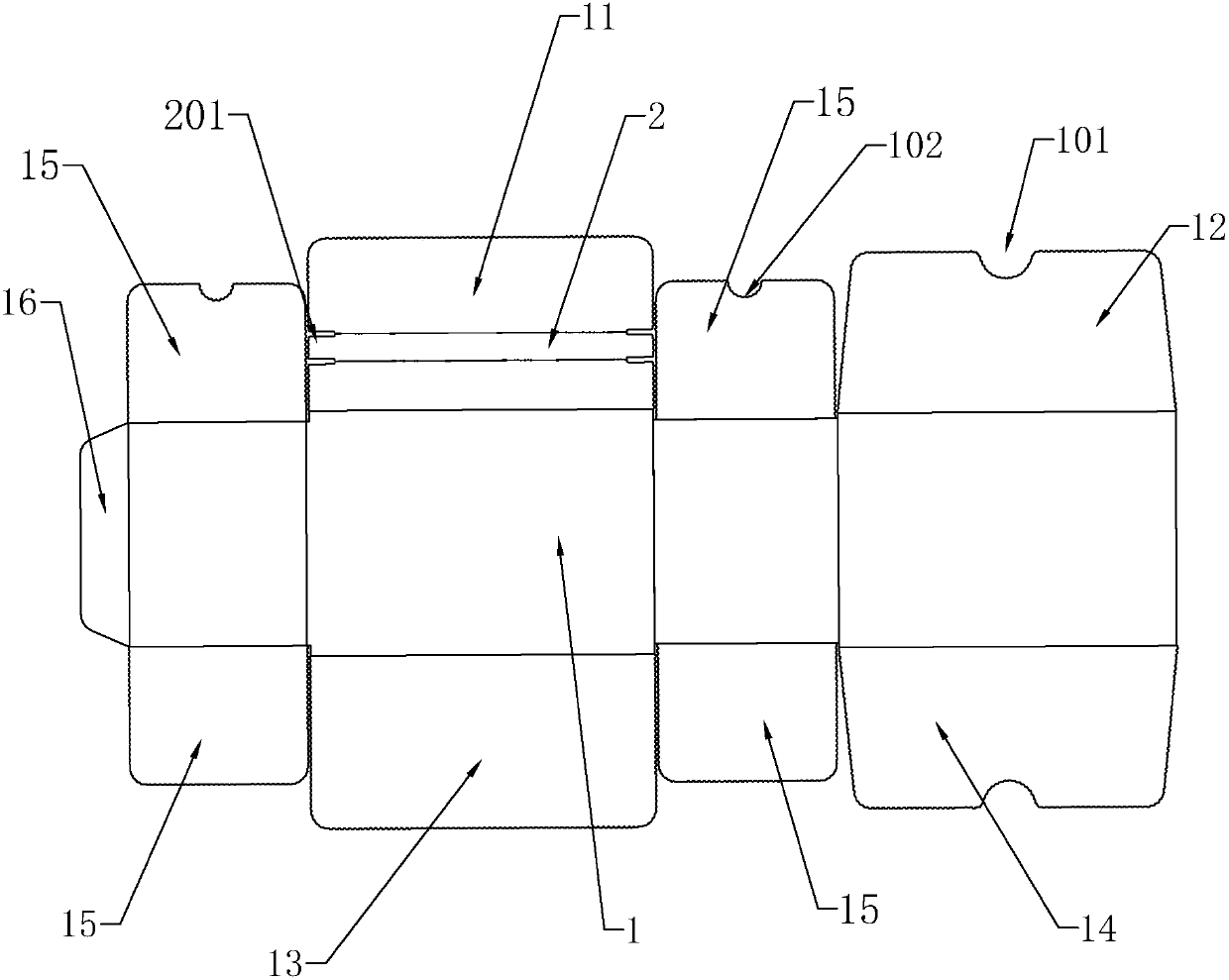
[0060] A box such as figure 2 As shown, in the unclosed state, the plane laying is clearly visible, including the box body 1 and the cover assembly integrally provided with the box body 1 and rotatably flipped and connected, including the first cover plate 11 arranged above the box body 1, The second cover plate 12 and two side plates 15 installed on both sides of the first cover plate 11, followed by the third cover plate 13, the fourth cover plate 14 and the third cover plate 13 installed on the bottom of the box body 1 There are two side plates 15 on both sides. In addition, a connecting plate 16 is provided on the left side of the box body 1 . The connecting plate 16 can also be arranged on the right side of the box body 1 in actual production.

[0061] The first cover plate 11, the second cover plate 12, the third cover plate 13, the fourth cover plate 14 and the side plates 15 on both sides of the first cover plate 11 are also provided with a first groove 101, a second ...

Embodiment 2

[0068] Compared with Example 1, as Figure 5 As shown, in Embodiment 1, the two ends of the tear strip, the ends of the protruding strip 201 and the two sides of the first cover plate 11 are arranged on each other. In practice, it is easy to be hung on the protruding strip 201 and cause the tear groove 104 to be damaged. , so that the end part of the tear strip is disconnected, so further improvements are needed on this basis; Figure 6 As shown, the two third grooves 103 forming the convex strip 201 are connected, and the two third grooves 103 are arranged in a "┒" shape, and the curved parts of the two third grooves 103 are connected.

Embodiment 3

[0070] Compared with Embodiments 1 and 2, in actual use of Embodiment 1 and Embodiment 2, after the tear strip is pulled off, the first cover plate 11 is divided into upper and lower parts, and cannot be closed again for use. , needs to be further improved on this basis; combined with Figure 12 and Figure 13 As shown, the first cover plate 11 is provided with a third gluing strip 33, the 3rd gluing strip 33 includes a gluing layer 3 and an isolation layer 4 covered on the gluing layer 3, the 3rd gluing strip 33 is located at the first Between a cover plate 11 and the connection end 01 of the box body 1 and the tear strip; there are two tabs 41 on the isolation layer 4 , and they are respectively installed at both ends of the isolation layer 4 .

[0071] After setting like this, after the user tears off the tear tape, the first cover plate 11 is divided into two parts, the first part will be stuck on the second cover plate 12 by the first glue strip 31, and the second part i...


PUM


Abstract

The invention discloses a packaging box and a manufacturing process thereof. The packaging box comprises a box body, a first cover plate, a second cover plate, a third cover plate, a fourth cover plate and side plates, the inner wall of the first cover plate and the inner wall of the third cover plate are each provided with a glue coating layer and an isolation layer covering the glue coating layer, and the gluing layer on the first cover plate is located between the reverse extending end, connected with the box body, of the first cover plate and a tearing belt. The packaging box is of a structure which is easy to tear and convenient to use, and when the packaging box is used actually, the box body can be sealed only by tearing the isolation layers on the surfaces of the glue coating layers and bonding the first cover plate and the second cover plate or the third cover plate and the fourth cover plate through glue; and when the packaging box needs to be opened, the end of the tearing belt is held by hand and pulled outwards with force, the tearing belt is separated from the first cover plate to divide the first cover plate into an upper part and a lower part, the upper part is connected with the second cover plate, and the lower part is connected with the box body.

Description

technical field [0001] The invention relates to the technical field of packaging box products, in particular to a packaging box and a manufacturing process of the packaging box. Background technique [0002] Packaging box, as the name implies, is a box used to package goods. It is mainly used to ensure the safety of goods in transportation. With the progress of the times and the rapid development of the e-commerce industry, more and more goods are packaged and sent in packaging boxes. Sales, thus greatly increasing the use of packaging boxes. [0003] The existing packing box basically adopts the method of closing the movable cover on the packing box and then bonding the outside with tape, and packing and sealing the packing box as a whole for delivery. This kind of packing process is more complicated and the work efficiency is relatively low. , The waste of adhesive tape is also serious; when the customer receives the express and needs to disassemble it, he has to use tool...

Claims


Application Information

Patent Timeline
Patent Type & Authority Applications(China)
IPC IPC(8): B31B50/20B31B50/25B31B50/62B31B50/74B65D5/54
CPCB65D5/541
Inventor 杭守冬
Owner HANGZHOU YONGHUA PRINTING & PACKING CO LTD
Why Eureka
Try Eureka