Supercharge Your Innovation With Domain-Expert AI Agents!

Automatic turnover device

A technology of automatic flipping and flipping motors, applied in the direction of transportation and packaging, conveyor objects, etc., can solve the problems of high cost, inconvenient clamping of mechanical arms, expensive mechanical arms, etc., and achieve the effect of high work efficiency and simple structure

Pending Publication Date: 2018-03-27
苏州弘瀚自动化科技有限公司
View PDF9 Cites 24 Cited by
  • Summary
  • Abstract
  • Description
  • Claims
  • Application Information

AI Technical Summary

Problems solved by technology

[0002] In the field of automatic production lines, it is often necessary to turn the workpiece over to facilitate processing operations on the back of the workpiece. The usual method is to use the first mechanical arm to pick up the workpiece and then turn it over, and then the second mechanical arm sucks the back of the workpiece. One robotic arm releases the workpiece, and finally the second robotic arm places the workpiece on the workbench, or the first robotic arm picks up the workpiece and turns it over, then puts the workpiece on the workbench through the tooling on the workbench, and then The mechanical arm is retracted, the mechanical arm is expensive in these two methods, the cost is high, and when the surface of the workpiece is uneven, the mechanical arm is inconvenient to clamp

Method used


Image

  • Automatic turnover device
  • Automatic turnover device

Examples


Embodiment Construction

[0017] The present invention will be further described below in conjunction with the accompanying drawings and specific embodiments, so that those skilled in the art can better understand and implement the present invention, but the cited embodiments are not intended to limit the present invention.

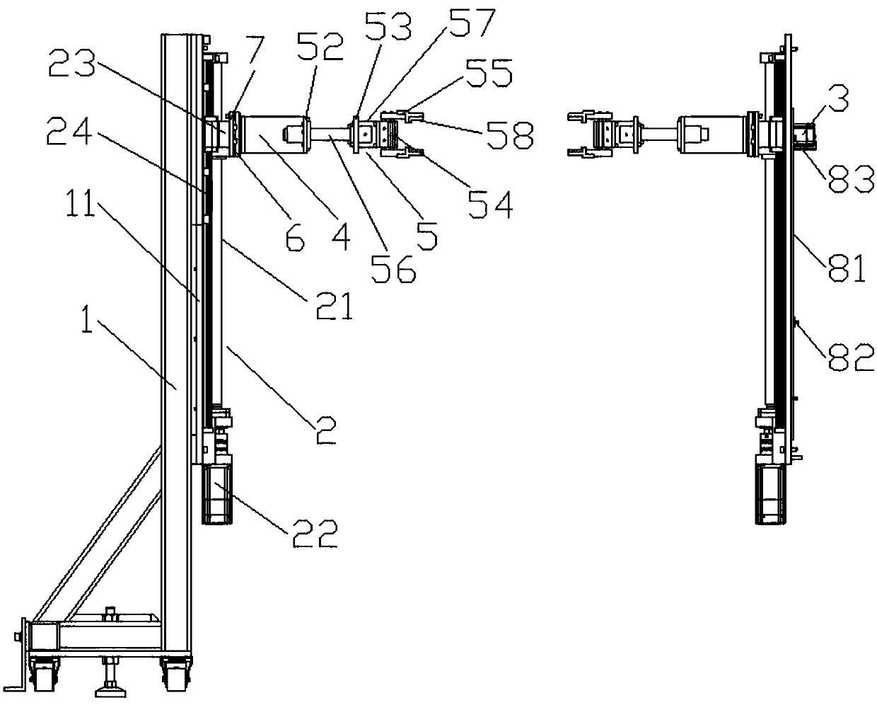
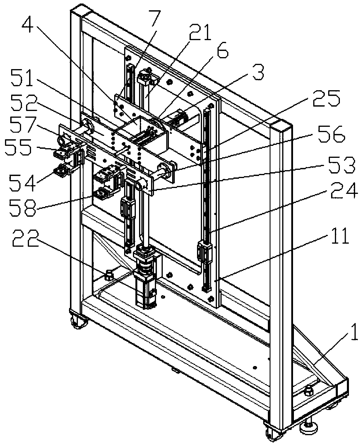
[0018] An automatic turning device includes two racks 1 arranged opposite each other. Each frame 1 includes a vertically installed lifting mechanism 2, a turning motor 3 fixed on the lifting mechanism 2, and a turning motor 3 connected to the output The rotating seat 4 on the shaft and the clamping mechanism 5 fixedly arranged on the rotating seat 4, after the clamping mechanism 5 clamps the workpiece on the worktable, the lifting mechanism 2 drives the turning motor 3 and the clamping mechanism 5 to move upward to the workpiece At a position where there will be no interference with the worktable, then the turning motor 3 works to drive the rotation base 4 and the clamping mechanism 5...


PUM


Abstract

The invention discloses an automatic turnover device. The automatic turnover device comprises two opposite racks, each rack comprises a lifting mechanism vertically mounted, a turnover motor fixed tothe lifting mechanism, a rotation base rotatably connected to an output shaft of the turnover motor and a clamping mechanism fixedly arranged on the rotation base, the clamping mechanisms clamp workpieces on a worktable, the lifting mechanisms drive the turnover motors and the clamping mechanisms to move upwards to the position until the workpieces and the work table cannot intervene, the turnovermotors work to drive the rotation bases and the clamping mechanisms to rotate, and the workpieces are turned over by 180 degrees. The workpieces in various shapes can be turned over, and the device is simple in structure and high in work efficiency.

Description

Technical field [0001] The invention relates to the field of automatic production, in particular to an automatic turning device. Background technique [0002] In the field of automatic production lines, it is often necessary to flip the workpiece to facilitate processing operations on the back of the workpiece. The usual practice is to use the first robotic arm to pick up the workpiece and flip it, and then the second robotic arm sucks the back of the workpiece. One robotic arm releases the workpiece, and finally the second robotic arm places the workpiece on the worktable, or the first robotic arm picks up the workpiece and turns it over and puts the workpiece on the worktable through the tooling on the worktable, and then The mechanical arm is retracted. In these two methods, the mechanical arm is expensive and costly, and when the surface of the workpiece is uneven, the mechanical arm is inconvenient to clamp. Summary of the invention [0003] The technical problem to be solve...

Claims


Application Information

Patent Timeline
Patent Type & Authority Applications(China)
IPC IPC(8): B65G47/90B65G47/248
CPCB65G47/248B65G47/902
Inventor 陈信宏
Owner 苏州弘瀚自动化科技有限公司
Features
  • R&D
  • Intellectual Property
  • Life Sciences
  • Materials
  • Tech Scout
  • Unparalleled Data Quality
  • Higher Quality Content
  • 60% Fewer Hallucinations
Learn More