Device and method for measuring geometric parameters of long and thin hole
A technology of geometric parameters and measuring devices, which is applied in the direction of measuring devices, optical devices, instruments, etc., to achieve the effect of improving measurement accuracy, small size of measuring head and good usability
- Summary
- Abstract
- Description
- Claims
- Application Information
AI Technical Summary
Problems solved by technology
Method used
Image
Examples
Embodiment 1
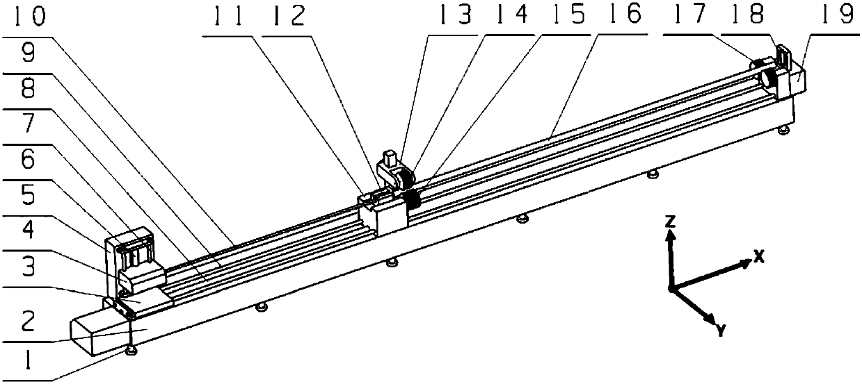
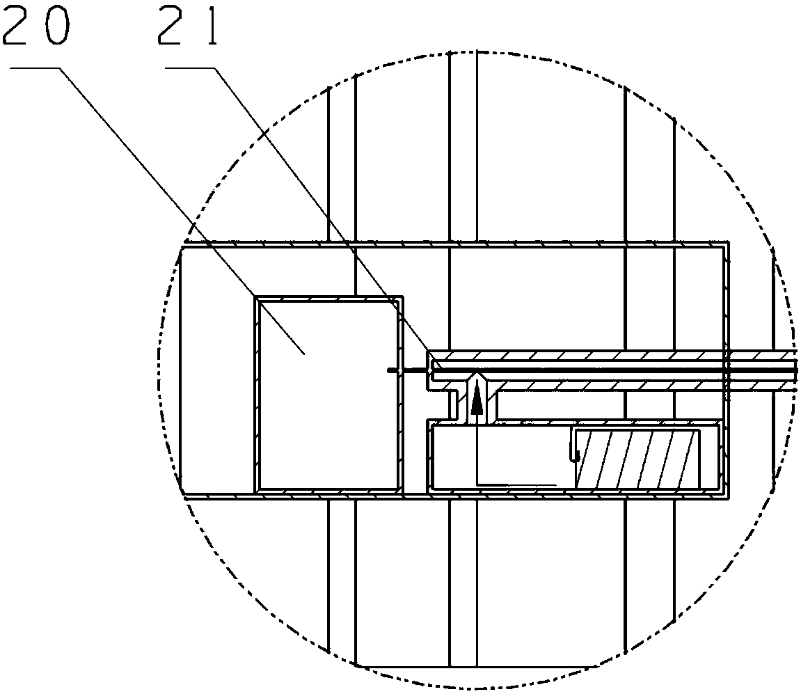
[0044] combine Figure 1 to Figure 5 As shown, the present embodiment provides a device for measuring the geometric parameters of elongated holes, which includes: a positioning mechanism, a traveling mechanism and a measuring mechanism; the positioning mechanism is used to automatically center the position of the workpiece 16 to be measured; the measuring The mechanism includes: self-centering measuring head 12, toughness measuring rod 10, laser 20, pneumatic sensor and CCD processor 18; said toughness measuring rod 10 is provided with an internal passage along its axial direction, and The first end is provided with an air inlet, and the second end of the toughness measuring rod 10 is provided with an automatic centering probe 12, and the automatic centering probe 12 includes: a pneumatic centering probe and a laser sight 22; The laser 20 is arranged on the walking mechanism, and the optical fiber 21 of the laser 20 is passed through the inner channel of the toughness measurin...
Embodiment 2
[0060] combine Figure 1 to Figure 5 As shown, the present embodiment also provides a method for measuring the geometric parameter of the elongated hole according to the first embodiment, which includes the following steps:
[0061] One), realizing the automatic centering of the workpiece 16 to be measured by the positioning mechanism; as a further technical solution, the automatic centering of the workpiece 16 to be measured by the positioning mechanism includes the following steps: wherein, the positioning mechanism includes: Workbench 2, positioning seat 11 and sliding seat 19; The first end of described traveling mechanism is arranged on described workbench 2, described slide seat 19 is arranged on the second end of described workbench 2, described The workbench 2 is arranged on the middle section of the workbench 2, and an elastic pressing mechanism 13 is arranged on the positioning seat 11. The elastic pressing mechanism 13 is provided with a rotating wheel 14, and on th...
PUM
 Abstract
Description
Claims
Application Information
 - R&D
- Intellectual Property
- Life Sciences
- Materials
- Tech Scout
- Unparalleled Data Quality
- Higher Quality Content
- 60% Fewer Hallucinations
Browse by: Latest US Patents, China's latest patents, Technical Efficacy Thesaurus, Application Domain, Technology Topic, Popular Technical Reports.
© 2025 PatSnap. All rights reserved.Legal|Privacy policy|Modern Slavery Act Transparency Statement|Sitemap|About US| Contact US: help@patsnap.com


