
Radar angle estimation and error correction method

An error correction and angle estimation technology, applied in the field of target detection, can solve the problems of unrealizable algorithm, poor robust performance, deterioration of azimuth estimation performance, etc., and achieve the effect of reducing mutual coupling error, amplitude and phase error, and small calculation amount.

Active Publication Date: 2018-03-27
AIR FORCE UNIV PLA
View PDF6 Cites 10 Cited by
  • Summary
  • Abstract
  • Description
  • Claims
  • Application Information

AI Technical Summary

Problems solved by technology

[0004] Since people's prior knowledge of the array model often has certain deviations, most of these algorithms cannot be realized in practical applications.
It has been found that various high-resolution spatial spectrum estimation algorithms have poor robustness to errors and are often very sensitive to model errors, and small model disturbances often lead to a sudden deterioration in the performance of orientation estimation.

Method used


Image

  • Radar angle estimation and error correction method
  • Radar angle estimation and error correction method
  • Radar angle estimation and error correction method

Examples


Embodiment Construction

[0035] In order to make the purpose, technical solutions and advantages of the embodiments of the present invention clearer, the technical solutions in the embodiments of the present invention will be clearly and completely described below in conjunction with the drawings in the embodiments of the present invention. Obviously, the described embodiments It is a part of embodiments of the present invention, but not all embodiments. The components of the embodiments of the invention generally described and illustrated in the figures herein may be arranged and designed in a variety of different configurations.

[0036] Accordingly, the following detailed description of the embodiments of the invention provided in the accompanying drawings is not intended to limit the scope of the claimed invention, but merely represents selected embodiments of the invention. Based on the embodiments of the present invention, all other embodiments obtained by persons of ordinary skill in the art wi...


PUM


Abstract

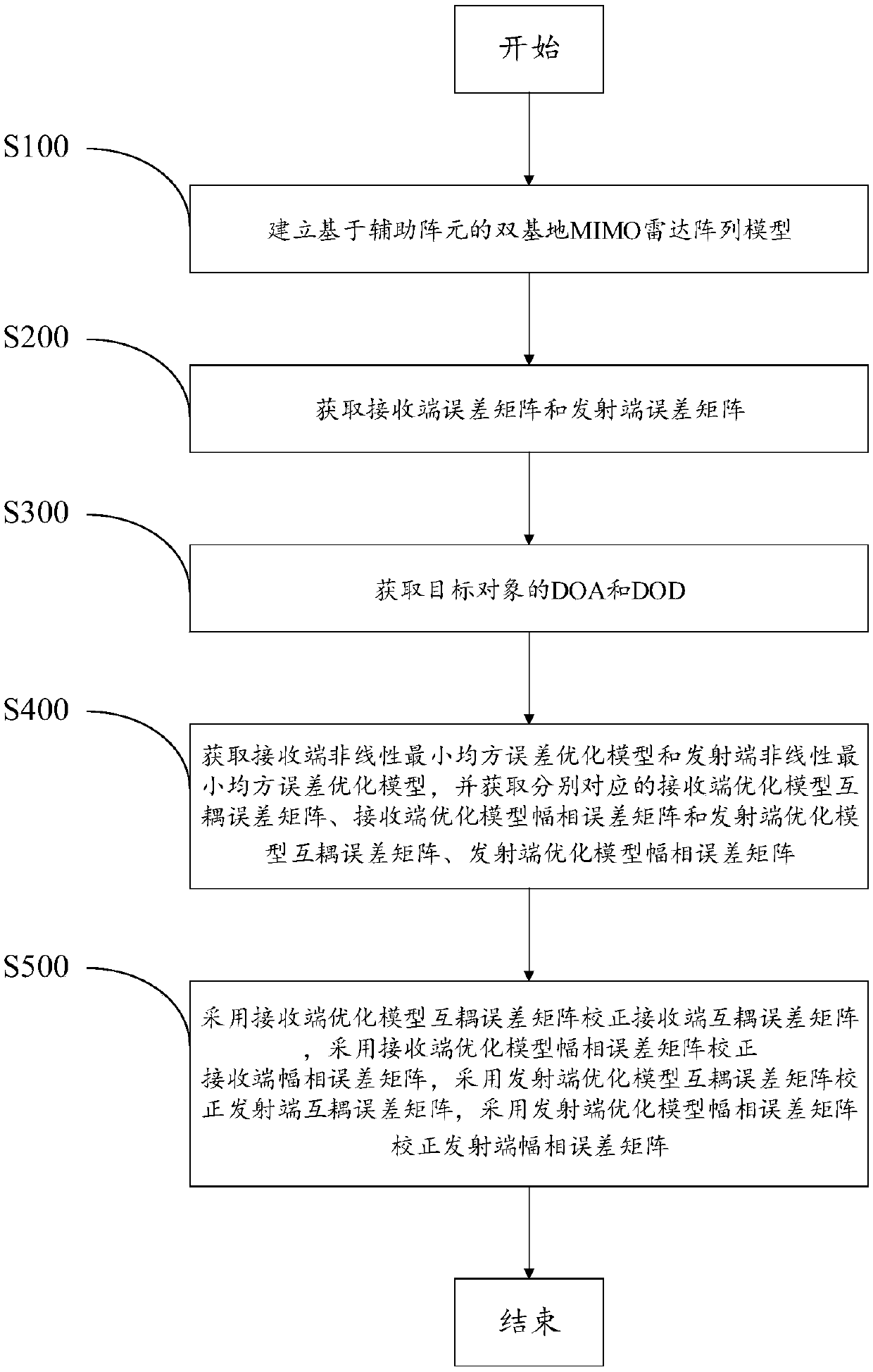
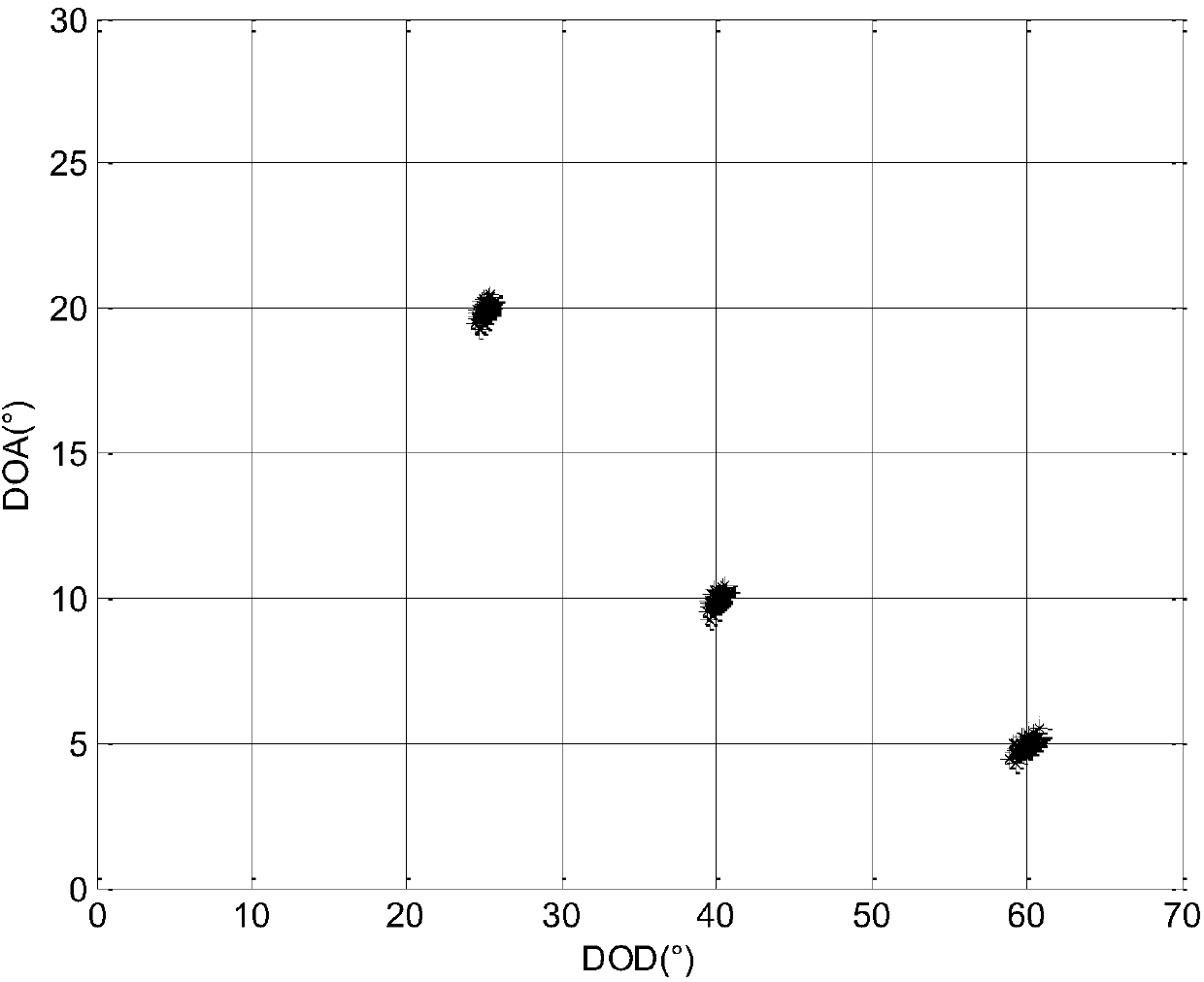
The present invention provides a radar angle estimation and error correction method and belongs to the target detection technological field. The method includes the following steps that: a radar arraymodel is established; the error matrixes of a receiving end and a transmitting end are obtained; the DOA (Direction of Arrival) and DOD (Direction of and Departure) of a target are obtained; the nonlinear least-mean-square error optimization models of the receiving end and the transmitting end are acquired, and the mutual coupling error matrix and amplitude-phase error matrix of the correspondingreceiving end optimization model and the mutual coupling error matrix and amplitude-phase error matrix of the corresponding transmitting end optimization model are obtained; and the mutual coupling error matrix of the receiving end optimization model is adopted to correct a receiving end mutual coupling error matrix, the amplitude-phase error matrix of the receiving end optimization model is adopted to correct a receiving end amplitude-phase error matrix, the mutual coupling error matrix of the transmitting end optimization model is adopted to correct a transmitting end mutual coupling errormatrix, and the amplitude-phase error matrix of the transmitting end optimization model is adopted to correct a transmitting end amplitude-phase error matrix. With the method of the invention adopted,the mutual coupling and amplitude-phase error of the transmitting-receiving array can be corrected, and the DOA (Direction of Arrival) and DOD (Direction of and Departure) of the target can be accurately calculated. The operation amount of the method is small.

Description

technical field [0001] The invention relates to the technical field of target detection, in particular to a radar angle estimation and error correction method. Background technique [0002] The bistatic multiple input multiple output (MIMO: Multiple Input Multiple Output) radar high-resolution angle estimation algorithm based on the array parameter model has attracted widespread attention for its excellent high-resolution performance. However, the huge computational load of high-resolution algorithms and the low robustness of algorithms to errors have always been important bottlenecks that limit their practical engineering applications. [0003] With the continuous update and development of high-speed digital signal processors, and people's in-depth research on parallel fast algorithms and sub-optimal algorithms, the problem of real-time implementation of high-resolution algorithms has been fundamentally alleviated. But the research of array error correction and robust angl...

Claims


Application Information

Patent Timeline
IPC IPC(8): G01S7/40G01S13/88
CPCG01S7/4004G01S13/88
Inventor 郭艺夺宫健冯为可张永顺李洪兵李志汇王强
Owner AIR FORCE UNIV PLA
Learn More