Supercharge Your Innovation With Domain-Expert AI Agents!

3D printer for metal alloy filament

A 3D printer, metal alloy technology, applied in metal processing equipment, manufacturing tools, additive manufacturing, etc., can solve the problems of shrinkage deformation, weak adhesion to each other, temperature difference of metal wires, etc.

Active Publication Date: 2018-03-27
赵庆一
View PDF10 Cites 1 Cited by
  • Summary
  • Abstract
  • Description
  • Claims
  • Application Information

AI Technical Summary

Problems solved by technology

[0006] In ordinary 3D printers, plastic wires or metal alloy wires melted in nozzles are laminated layer by layer on a heated base plate in a space open to the outside, so there are disadvantages as follows: Severe temperature difference makes the adhesion between each other weak, and the shrinkage effect caused by the cooling of the three-dimensional shape is seriously deformed

Method used


Image

  • 3D printer for metal alloy filament
  • 3D printer for metal alloy filament
  • 3D printer for metal alloy filament

Examples


specific Embodiment approach

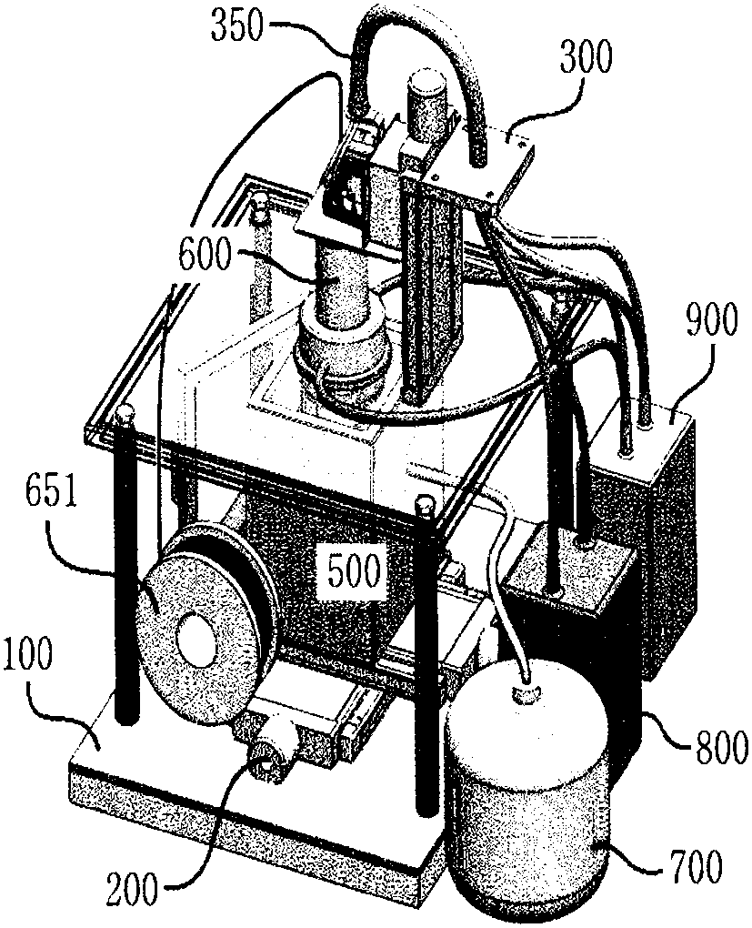
[0042] Figure 4 It shows the overall structure of the nozzle body 600. The metal alloy wire 650 originating from the circular reel 651 utilizes the transfer gear 652 connected to the transfer motor located at the upper end of the nozzle body, and passes through the inside of the tubular nozzle body. The nozzle 610 located at the lower end of the nozzle body 600 is moved.

[0043] The high-frequency current generated by the high-frequency generator 660 provided at the upper end of the nozzle body is supplied to the induction heating coil 620 provided at the lower end of the nozzle body through the fixed electrode 680 .

[0044] Cooling is formed inside the lower part of the nozzle body by connecting the inner pipe 640 forming the cooling water hose 670 along the plumb direction and the cooling water hose 670 originating from the connection line 350 arranged at the upper end of the nozzle body. The induction heating coil 620 and the cooling cylinder 630 of the water channel su...


PUM


Abstract

The present invention relates to a 3D printer using a metal alloy filament, wherein the 3D printer introduces a metal alloy filament (650) through a nozzle (610) formed inside an induction heating coil (620), melts and extrudes the filament, and laminates the filament three-dimensionally inside a chamber (500) heated to a similar temperature. The present invention forcibly introduces a metal alloyfilament in a nozzle, heated by an induction heating coil which circularly encloses the exterior of the nozzle and forms a cooling passage therein, by means of a transfer gear connected to a transfermotor. A 3D printer for a metal alloy filament is provided in which, in order to prevent the oxidation of a metal alloy laminate (520), an inert gas is introduced, the outside and heat and air are blocked, and a metal alloy filament (650) that is melted in a nozzle and extruded is laminated one layer at a time on a floor plate (510) installed inside a heated chamber (500) and moving three-dimensionally with respect to the nozzle, in order to firmly attach the filament having little deformation.

Description

technical field [0001] The present invention relates to a three-dimensional printer in which a metal alloy wire 650 is melted and extruded in a nozzle 600 to generate a three-dimensional laminate 520 on a bottom plate 510, and more specifically relates to a three-dimensional printer for a metal alloy wire, which utilizes a high-frequency induction heating coil 620 The nozzles are heated and the metal alloy wires are melted and extruded to be laminated layer by layer on the lower bottom plate located inside the chamber 500 heated at a similar temperature, thus firmly adhering and extruding each other Deformation is minimized. Background technique [0002] For existing 3D printers, in nozzles heated by heaters or high-frequency induction heating, the supplied thermoplastic wires or metal alloy wires are melted and extruded, and are carried out layer by layer on the base plate. Layered to complete the three-dimensional shape. [0003] Reference Patent Document 1: Patent CN 20...

Claims


Application Information

Patent Timeline
IPC IPC(8): B22F3/115B29C64/118B33Y30/00B33Y40/00B33Y70/00
CPCB33Y30/00B33Y40/00B22F2003/208B22F2202/07B22F2999/00Y02P10/25B22F12/20B22F12/53B22F12/10B22F10/22B33Y40/10B33Y50/00B22D23/003B22D46/00
Inventor 赵庆一
Owner 赵庆一
Features
  • R&D
  • Intellectual Property
  • Life Sciences
  • Materials
  • Tech Scout
  • Unparalleled Data Quality
  • Higher Quality Content
  • 60% Fewer Hallucinations
Learn More