
Washing machine driving device, washing machine having the same, and washing machine driving method

The technology of a driving device and a driving method is applied to the control device of a washing machine, a washing machine with a container, and an electromechanical device, etc., which can solve problems such as a brushless DC motor driving method, slow dynamic response, and low rotor inertia that have not yet been proposed, and achieve The effect of shortening the overall washing time, high durability, and high-efficiency washing stroke

Active Publication Date: 2020-08-14
AMOTECH
View PDF8 Cites 0 Cited by
  • Summary
  • Abstract
  • Description
  • Claims
  • Application Information

AI Technical Summary

Problems solved by technology

[0015] The induction motor has the characteristics of low noise, low vibration, etc. However, since the induction motor is an asynchronous motor with low torque characteristics at low speed and slow dynamic response, it is difficult to rotate clockwise and counterclockwise when it is in the washing process. Quickly change the direction of rotation and form a strong washing water flow
[0016] On the contrary, the brushless DC (BLDC) motor is a dynamic motor with fast dynamic response, low rotor inertia, and simple speed control. However, conventionally, as a driving device for washing machines, there has been no proposal to highlight the characteristics of such a brushless DC motor. drive method

Method used


Image

  • Washing machine driving device, washing machine having the same, and washing machine driving method
  • Washing machine driving device, washing machine having the same, and washing machine driving method
  • Washing machine driving device, washing machine having the same, and washing machine driving method

Examples


Embodiment 1

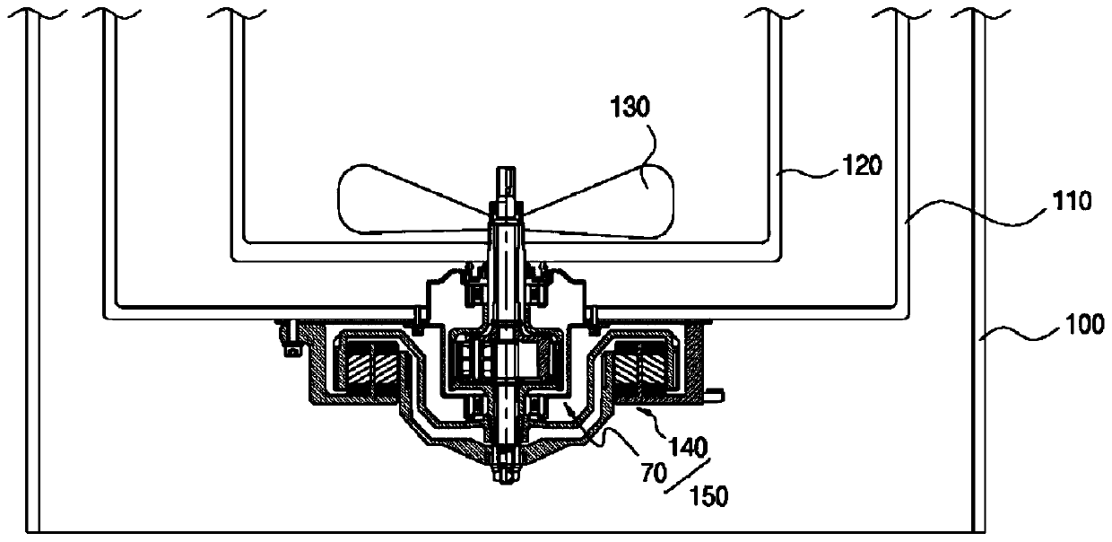
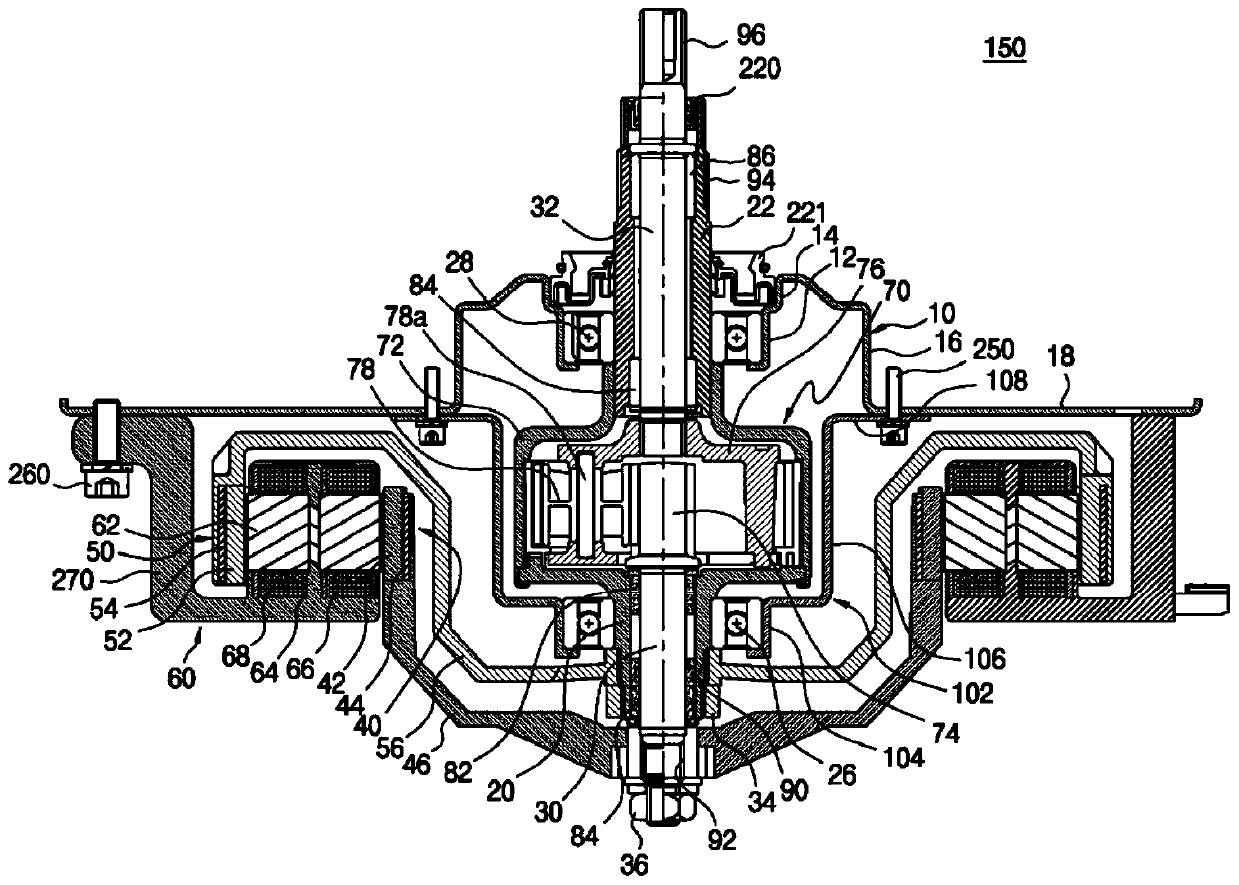
[0255] Reference Figure 13 The rotation speed timing chart for forming the opposite direction washing water flow. In the opposite direction washing water flow forming method of Embodiment 1 of the present invention, basically, the pulsator 130 rotates in one direction, for example, clockwise, that is, clockwise. Drive, within a preset time, after maintaining the motor on time, there is a prescribed stop time for direction change.

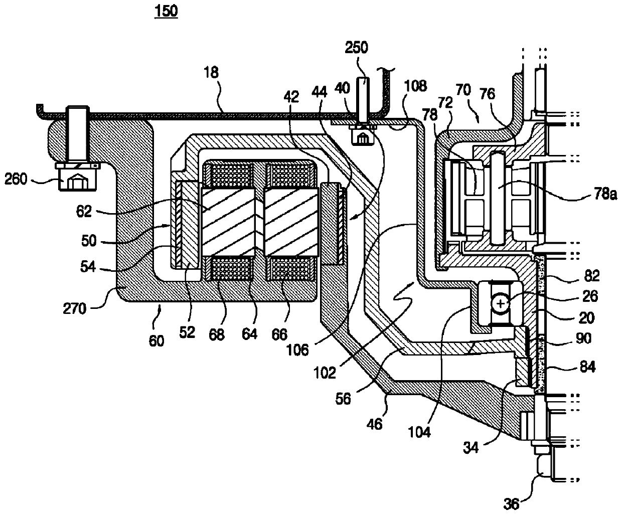
[0256] Figure 13 Here, the graph P is the rotation speed of the inner rotor 40 for driving the pulsator 130, and the graph S is the rotation speed of the outer rotor 50 for driving the spin basket.

[0257] After that, the pulsator 130 rotates in another direction, for example, in a counterclockwise direction, that is, a counterclockwise direction. After maintaining the motor on time for a preset time, there is a predetermined stop time for direction switching.

[0258] If the clockwise and counterclockwise driving of the pulsator 130 is completed, one c...

Embodiment 2

[0271] Reference Figure 14 , The method of forming the washing water flow in the opposite direction of Example 2 is the same as Figure 13 Example 1 shown is similar.

[0272] In the first embodiment, at the time of the initial driving and before the end of the motor on time, the inner rotor 40 is overdriven from 800 RPM to 1000 RPM and then stopped. In the second embodiment, the overdrive is not implemented. In order to generate vortex, drive the washing tub 120 in the direction opposite to the direction of rotation of the pulsator 130 within 1 second at the time of the initial driving of the motor on time and before the end of the motor-on time. The number of vortex occurrences is increased by one more time. Change the driving method.

[0273] That is, in Embodiment 2, as the inner rotor 40 is driven, the pulsator 130 is rotated clockwise at 800 RPM, while the outer rotor 50 is driven counterclockwise for 1 second to turn the washing tub 120 counterclockwise. It rotates at (-)5...

Embodiment 3

[0280] Reference Figure 15 The method for forming the washing water flow in the opposite direction in Embodiment 3 is similar to Embodiment 1 and Embodiment 2 as a whole.

[0281] The difference between Example 3 and Example 1 and Example 2 is as follows. When the motor is turned on at the initial driving time and before the end, it replaces the inner rotor 40 with an overshoot drive from 800 RPM to 1000 RPM, increasing the rotation speed of the inner rotor 40 to a maximum of 1000 RPM. To drive the rotation speed and drive torque of the pulsator 130.

[0282] Also, in the middle part of the motor on time, the rotation speed of the inner rotor 40 is reduced from 1000 RPM to 800 RPM, and by inserting the high speed adjustment section Pd, a powerful rippling washing water flow with large waves is generated.

[0283] Especially, in Example 3, the motor on time is shorter than that in Examples 1 and 2, and the stop time is longer. When the motor is on for the time, the rotation speed o...


PUM


Abstract

The present invention relates to a washing machine driving device, a washing machine having the same, and a washing machine driving method thereof, that is, by combining a double-rotor double-stator double-power drive motor and a planetary gear device to form a reverse-direction drive based on a pulsator and a washing tank When the washing water flows in the opposite direction, the energy consumption can be minimized, and a powerful three-dimensional washing water flow with high washing degree can be formed. The above-mentioned washing machine driving device includes: a driving motor of a double-rotor double-stator manner, having an inner rotor and an outer rotor independently controllable through the double stators; The resulting variable speed output is controlled by means of a second input applied from the remaining rotor to the ring gear. When performing a washing process, the pulsator has a stop time when switching the rotation direction clockwise and counterclockwise, and the washing tub is driven in the opposite direction to the rotation direction of the pulsator before the end of the driving time.

Description

Technical field [0001] The present invention relates to a washing machine driving device, a washing machine having the same, and a washing machine driving method. That is, when the opposite direction washing water flow based on the opposite direction driving of the pulsator and the washing tank is formed, the energy consumption can be minimized and the high The powerful three-dimensional washing water flow of washing degree. Background technique [0002] In a conventional fully automatic washing machine with a dehydration function, a rotating tank as a washing tank and dehydration tank is rotatably installed in the outer tank, and an agitating body (pulsator) is rotatably installed in the rotating tank Inside the bottom. The agitating body and the rotating tank are rotated by a drive motor. Therefore, during the washing operation, the rotation of the driving motor is transmitted to the agitating body while the rotating tank is braked and the rotating tank is rotated at a relativ...

Claims


Application Information

Patent Timeline
Patent Type & Authority Patents(China)
IPC IPC(8): D06F37/40D06F37/12D06F33/32D06F33/44
CPCD06F37/40D06F23/04D06F37/12Y02B40/00D06F37/304D06F33/46H02K16/00D06F2103/24D06F2105/46
Inventor 金炳秀宋德铉
Owner AMOTECH
Learn More