
Offshore structure, supporting member, skid shoe, and method for moving cantilever

A technology for offshore structures and supporting components, which is applied in the direction of supporting devices, underwater structures, infrastructure engineering, etc., can solve the problems of the limitation of lateral movement of the drilling rig and the inability to reach the required width of the drilling envelope, and achieve a simple structure Effect

Active Publication Date: 2018-03-27
GUSTOMSC BV
View PDF7 Cites 0 Cited by
  • Summary
  • Abstract
  • Description
  • Claims
  • Application Information

AI Technical Summary

Problems solved by technology

In jack-ups that do not have a wide extremity and thus do not have a large spacing between the rear legs, such as in boat-type self-propelled lifts, this limitation will be even more severe
Therefore, in such a jack-up, the lateral movement of the drilling rig will be limited and the required width of the drilling envelope may not be achieved

Method used


Image

  • Offshore structure, supporting member, skid shoe, and method for moving cantilever
  • Offshore structure, supporting member, skid shoe, and method for moving cantilever
  • Offshore structure, supporting member, skid shoe, and method for moving cantilever

Examples


Embodiment Construction

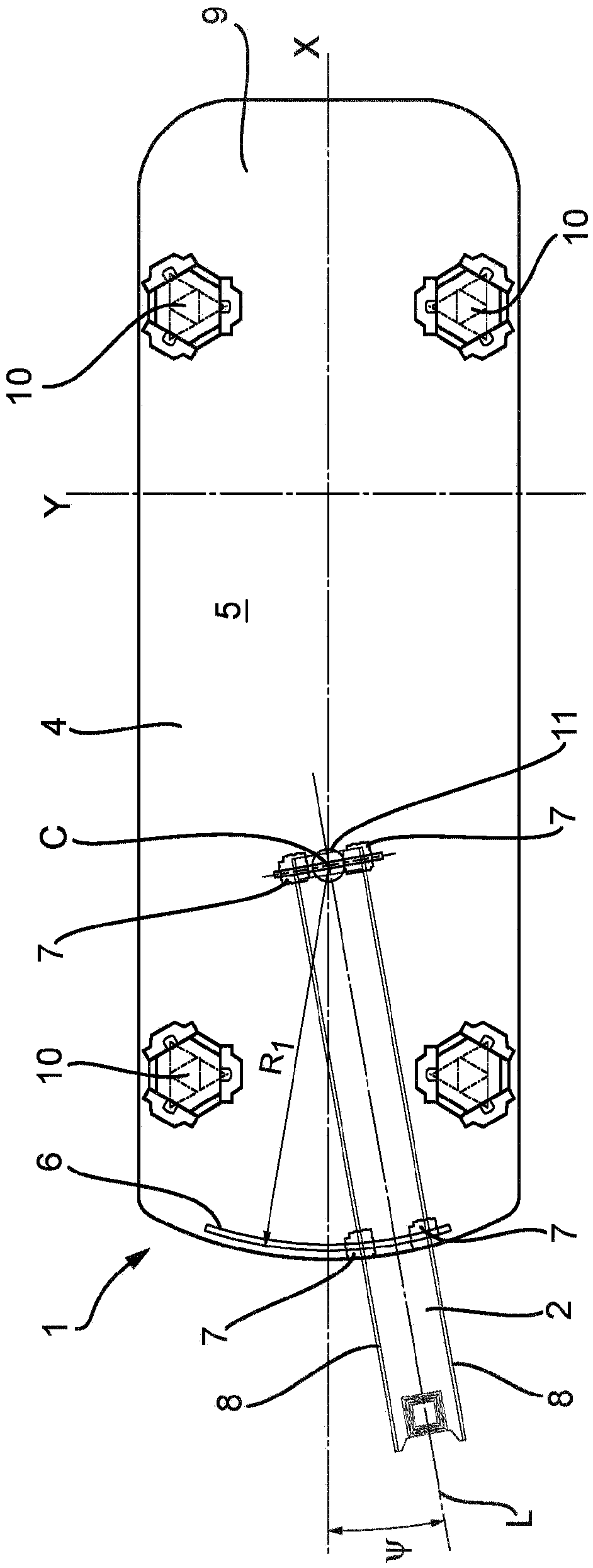
[0091] Typically, the skid system 1 comprises one or more guides, also referred to as deck rails 6, located on the deck 5 for guiding the movement of the support member 7 relative to the deck 5, wherein the skid system 1 is used for 4 (such as a boat or a jack-up) to move the boom 2. The deck rails 6 can be positioned on either side of, in front of or behind the point of rotation C of the boom 2 . The boom 2 itself is provided at its bottom side with a longitudinally extending guide or boom rail 8 . In the embodiment shown here, the offshore structure 9 comprises a platform 4 , a cantilever 2 and three or four legs 10 , wherein the legs 10 are adjustable relative to the platform 4 in a known manner.

[0092] The center line of the platform 4 ship is the X direction. The Y direction is perpendicular to the X direction in the horizontal plane. The axis of rotation extends in a vertical Z direction, wherein the Z direction is perpendicular to the deck plane of the X and Y dire...


PUM


Abstract

Method for moving a cantilever with respect to a deck of an offshore structure in longitudinal and rotational direction, around a predetermined virtual vertical axis, without providing a fixed vertical rotation shaft, comprising providing an offshore structure with a cantilever movable with respect to a deck of the offshore structure, providing cantilever rails on the bottom side of the cantileverand providing a supporting member or a skid shoe to support the cantilever on the deck, wherein the supporting member or the skid shoe has a top part configured for allowing the cantilever rail to have an angle deviating from the centerline of the skid shoe during rotation of the cantilever.

Description

technical field [0001] The invention relates to a drilling jack-up machine with a cantilever. Background technique [0002] Drilling jacks are in many cases equipped with a drilling crane mounted on the tail end of the jib, wherein the drilling crane is movable on the end (or side) of the jack. In order to drill multiple wells or cross a row of existing wells, the rig crane needs to cover a drilling envelope defined by a certain length or width. [0003] The longitudinal movement of the drilling crane is done by moving the boom in the longitudinal direction. This is done by the sliding system performing what is known as the X-motion of the cantilever. In the suspension state of the jack-up, the boom is fully retracted. After raising the jack in situ, the jib can be moved in the X direction to the desired longitudinal position. [0004] Lateral movement (or Y movement) of the drilling rig crane can be accomplished by moving the rig crane in a lateral direction on the boom...

Claims


Application Information

Patent Timeline
Patent Type & Authority Applications(China)
IPC IPC(8): E02B17/02E21B15/00
CPCE21B15/003E02B17/021E02B2017/0056E21B15/02
Inventor 米歇尔·克雷克尔威廉默斯·科恩雷德斯·约翰内斯·约瑟夫斯·沃尔德林马克·科尼利厄斯·马里努斯·弗朗西斯·罗门斯
Owner GUSTOMSC BV
Learn More