
Spring structure having multiple coil-shaped unit springs and method for manufacturing same

A technology of a spring unit and a manufacturing method, which is applied in the direction of springs, manufacturing tools, and springs from wires, etc., can solve the problems of functional limitation, insufficient range, insufficient tension and compression force, and insufficient bending force.

Inactive Publication Date: 2018-03-27
金炯佑 +1
View PDF6 Cites 2 Cited by
  • Summary
  • Abstract
  • Description
  • Claims
  • Application Information

AI Technical Summary

Problems solved by technology

[0005] However, because the conventional coil spring is manufactured by coiling a rod-shaped rod made of an elastic metal material into a helical shape, internal cracks and residual stress may occur due to plastic deformation that occurs during coiling and manufacturing. problems, and thus lead to morphological limitations and other functional limitations of the manufactured coil springs
[0006] In addition, in the existing structure of forming a single helical spring on the support portion of the non-spring structure described in Japanese Laid-Open Patent Publication No. 10-122285 (published on May 12, 1998), there is no use for In the case of a structure such as a casing that wraps the outer diameter of the spring, if a force is biased to one side away from the central axis of the inner diameter of the spring, the pitch (or wire) pitch in the direction of the force will be significantly different. The phenomenon that the reduction of pitch (or wire) spacing on the opposite parts based on the central axis of the inner hole is relatively small, and at the same time, the spring itself will be seriously bent when the thickness of the spring wire is insufficient.
That is, it will lead to the problem that the received force cannot be evenly distributed to the whole spring
[0007] In addition, the structure of forming a single helical spring on the support part of the non-spring structure may also cause insufficient tension and compression force and bending force
In addition, when the same number of helical spring units are used from the upper end to the lower end of the helical spring part, the number of tooth pitches and gaps, the material of the base material, and the values ​​of the outer diameter and inner diameter of the helical spring part can be used. It is difficult for a spring structure to expand its elastic range so that a spring can exhibit elastic effects on impact forces of different sizes
That is to say, in the existing spring structure, the range from the magnitude of the force that starts to show the elastic effect when being pressed or impacted to the magnitude of the force that no longer exhibits more elastic effect even if it is impacted is not large enough, and the elasticity Effect intelligence reacts to continuous force

Method used


Image

  • Spring structure having multiple coil-shaped unit springs and method for manufacturing same
  • Spring structure having multiple coil-shaped unit springs and method for manufacturing same
  • Spring structure having multiple coil-shaped unit springs and method for manufacturing same

Examples


Embodiment Construction

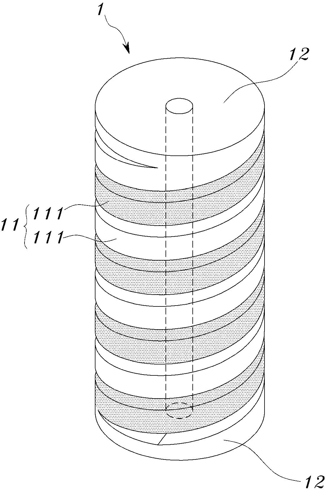
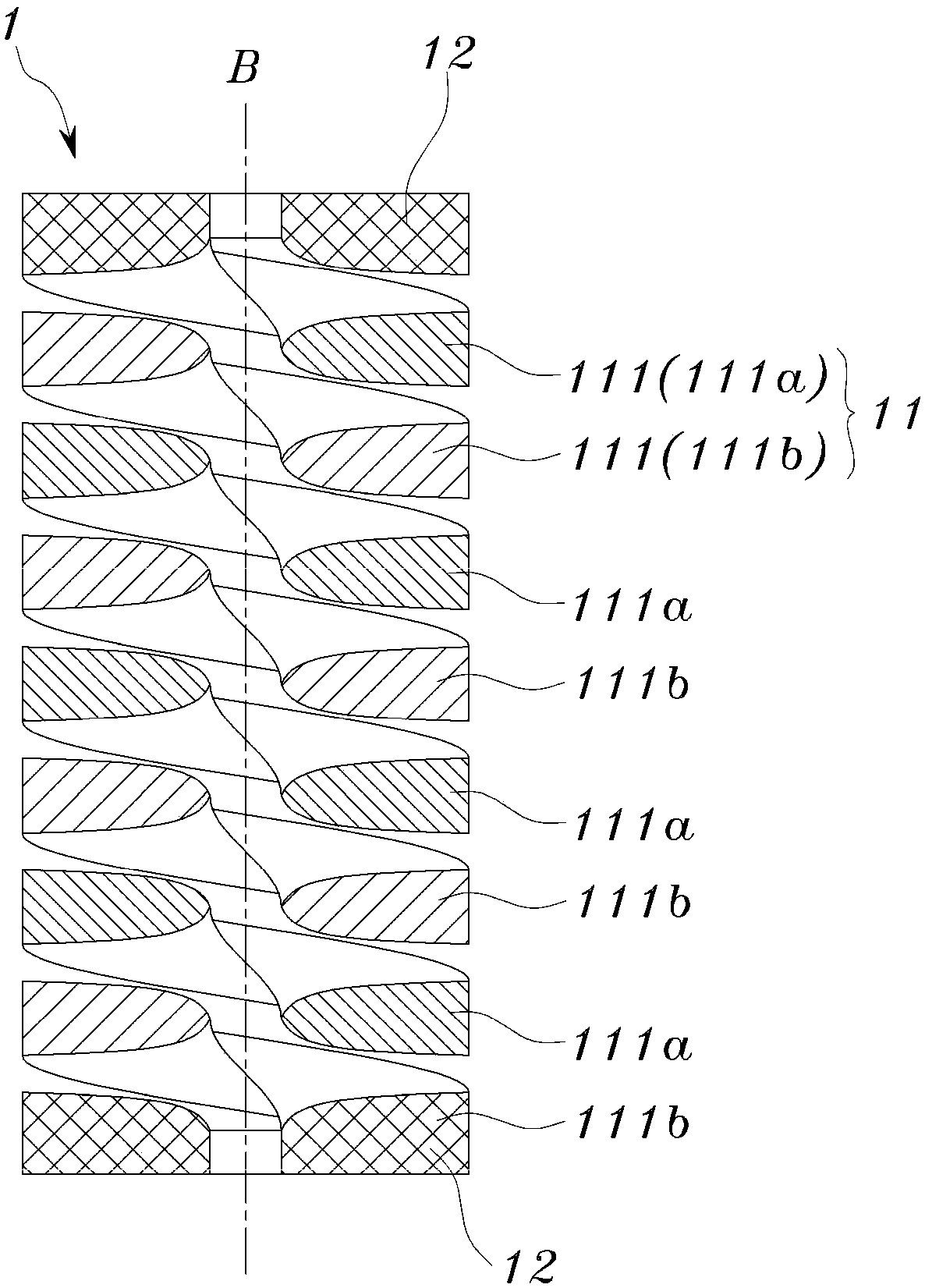
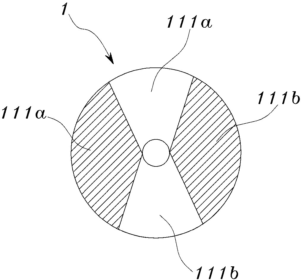
[0084] Next, a spring structure having a helical spring portion composed of a plurality of helical springs to which the present invention is applied and a method of manufacturing the same will be described in detail with reference to the drawings. Unless otherwise defined, the meanings of all terms used in this specification are the same as the general meanings of the relevant terms commonly understood by those skilled in the art to which the present invention belongs, and when the terms used in this specification In the event of conflicting meanings, the definitions used in this specification shall prevail. Throughout the specification, when it is stated that a certain part "contains" a certain constituent element, unless otherwise clearly stated to the contrary, it does not exclude the existence of other constituent elements, but means that other constituent elements can also be included.

[0085] Below, will combine Figure 1 to Figure 3 A spring structure with a plurality...


PUM


Abstract

The present invention relates to a spring structure and a method for manufacturing same, and more specifically, to a spring structure and a method for manufacturing same, the spring structure comprising: a support portion having a non-spring structure provided on both ends or on one end of the spring structure; and a coil-shaped spring portion comprising multiple coil-shaped unit springs having the same inner circumference and vertical central axis that are each connected to the support portion, so that a wire forming one of the coil-shaped unit springs is positioned between a wire forming another coil-shaped unit spring so as to be positioned adjacently thereto in an overlapping alignment with a regular vertical distance therebetween, thereby providing the support portion and the coil-shaped spring portion that are integrally formed.

Description

technical field [0001] The present invention relates to a spring structure and its manufacturing method, in particular to a support part forming a non-spring structure at both ends or one end, by connecting a plurality of helical spring units with the same inner diameter vertical to the central axis respectively A spring structure in which the support portion and the helical spring portion are integrally formed to form a helical spring portion neatly stacked at a certain vertical interval, and a method for manufacturing the same. Background technique [0002] A spring is a mechanical element that absorbs and accumulates energy by using the elastic deformation of an object to act as a buffer. It can be used in various products such as medical equipment, spring scales, furniture such as beds and sofas, safety valves, and automobiles. The above-mentioned spring is made of various raw materials such as metal, and can adopt various shapes such as spiral shape, ring shape, disc sh...

Claims


Application Information

Patent Timeline
Patent Type & Authority Applications(China)
IPC IPC(8): F16F3/02F16F3/04B21F35/00
CPCF16F3/04B23C3/32B23P15/00B21F35/00F16F3/02F16F2230/0029F16F2234/02F16F2238/026
Inventor 金炯佑金均奂
Owner 金炯佑
Learn More