
Electronic device housing

A technology for electronic devices and housings, applied in the field of electronic device housings, achieves the effects of low-cost manufacturing, avoiding housing expansion, and simple structure

Inactive Publication Date: 2021-05-18
BROSE FAHRZEUGTEILE GMBH & CO KG HALLSTADT (DE)
View PDF9 Cites 0 Cited by
  • Summary
  • Abstract
  • Description
  • Claims
  • Application Information

AI Technical Summary

Problems solved by technology

This additional containment requires an additional manufacturing step in manufacture, which entails additional costs

Method used


Image

  • Electronic device housing
  • Electronic device housing
  • Electronic device housing

Examples


Embodiment Construction

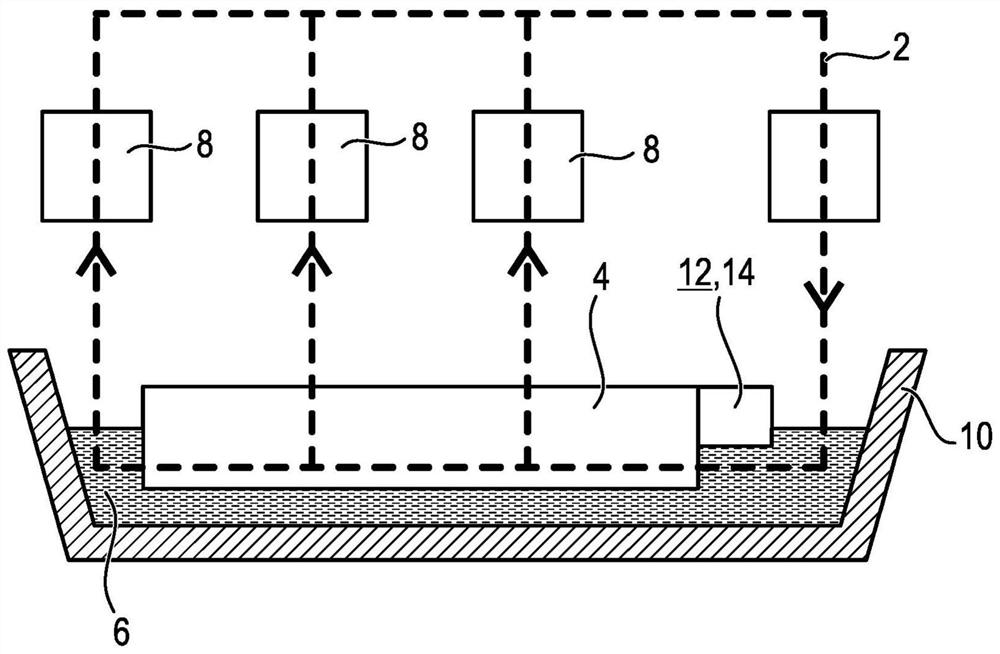
[0043] figure 1 An oil circuit 2 of a motor vehicle is shown schematically. The oil circuit 2 includes an electric pump or an oil pump 4 for delivering a fluid 6 , in particular mineral (lubricating) oil as a lubricant for especially moving transmission components 8 of the motor vehicle transmission. The transmission component 8 is a moving component or component of the motor vehicle transmission, for example a bearing or an actuator. The oil circuit 2 also has an oil sump 10 for receiving excess oil 6 .

[0044] The pump electronics 12 is signal-coupled to the oil pump 4 for regulating and controlling the electric motor (not shown in detail) of the oil pump 4 . The pump electronics 12 are arranged in a fluid-tight electronics housing 14 to protect them from oil 6 .

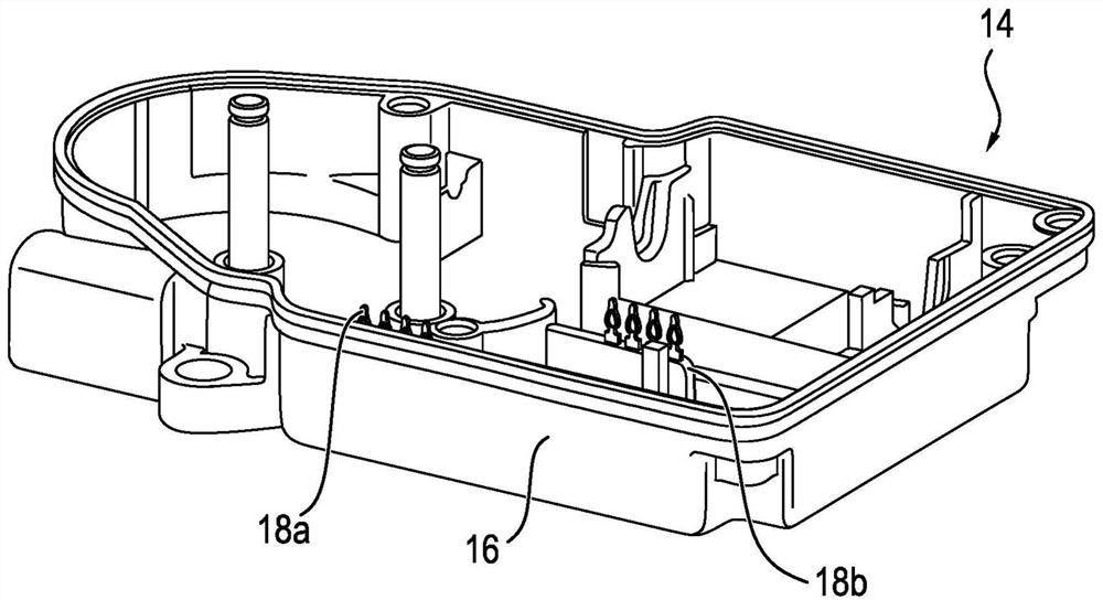
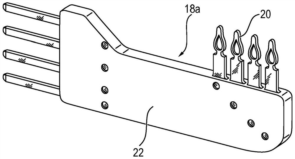
[0045] as in figure 2 As can be seen in , the electronics housing 14 includes a housing cover 16 and two electrical plugs 18 a and 18 b at least partially passing through the housing cover 16 . Pump electro...


PUM


Abstract

The invention relates to an electronics housing (14), in particular an electronics housing for pump electronics (12) of an electric auxiliary pump (4) for conveying a fluid (6) of a motor vehicle, the electronics housing The body has a housing cover (16) and an electrical plug (18), wherein the plug (18) passes through the housing cover (16) at least partially, and wherein the plug (18) is at least partially in contact with the fluid (6) When expanded the first material wraps.

Description

technical field [0001] The invention relates to the field of pumps, preferably electrically or electrically operated or driven pumps, and to an electronics housing for pump electronics. The invention still further relates to a pump with such an electronics housing and to a method for producing or assembling such an electronics housing. A pump is understood here to mean, in particular, an auxiliary or main pump in or for a motor vehicle. Background technique [0002] Electric oil pumps and in particular also so-called auxiliary pumps or auxiliary pumps are used to deliver oil for control tasks or to control especially moving parts or components, such as vehicles driven by internal combustion engines, hybrid technology or electrically (motor vehicle) for heat dissipation. Such oil pumps generally generate an oil circuit with pressure flow and volume flow due to their delivery properties. For example, electrically driven or electrically driven auxiliary pumps or auxiliary pu...

Claims


Application Information

Patent Timeline
Patent Type & Authority Patents(China)
IPC IPC(8): H02K5/22H01R13/52H02K11/33H02K5/10H02K7/14
CPCH02K5/10H02K5/225H02K7/14H02K11/33
Inventor 乌韦·克利佩特克里斯多佛·奥托
Owner BROSE FAHRZEUGTEILE GMBH & CO KG HALLSTADT (DE)
Learn More