
Deburring machine

A deburring machine and machine head technology, which is applied to surface polishing machine tools, machine tools suitable for grinding workpiece planes, metal processing equipment, etc., can solve problems such as low efficiency, difficulty in controlling the weight of hands, and inability to meet the quality requirements of workpieces, etc. , to achieve the effect of improving the effect

Inactive Publication Date: 2018-03-30
LANUSS LNDUSTRIAL EQUIP SUZHOU CO LTD
View PDF7 Cites 11 Cited by
  • Summary
  • Abstract
  • Description
  • Claims
  • Application Information

AI Technical Summary

Problems solved by technology

[0003] In the field of metal processing, the most common method is manual deburring, using files, sandpaper, grinding heads, etc. as auxiliary tools to wipe off the burrs on the surface of the workpiece. This method consumes a lot of manpower and is inefficient; Due to the influence of manpower, it is difficult to control the weight of the hand. Excessive force will scratch the surface of the workpiece and affect the surface quality of the workpiece. For many workpieces that have been blanked, such as thin-plate dense-hole workpieces, stainless steel stamping parts, and corner appearance requirements Very tall workpieces are difficult to manually deburr, and manual deburring can no longer meet the quality requirements of the workpiece
[0004] In order to solve the above problems, there are currently methods of using mechanical deburring in the prior art. However, mechanical deburring can only achieve part of the functions on a single machine, and it is impossible to deburr and wire-draw the surface of metal materials with multiple coverages.

Method used


Image

  • Deburring machine
  • Deburring machine
  • Deburring machine

Examples


Embodiment Construction

[0040] The technical solutions of the present invention will be further described below in conjunction with the accompanying drawings and through specific implementation methods.

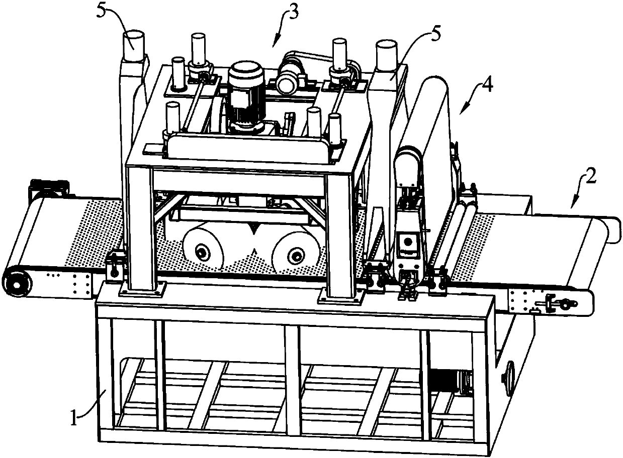
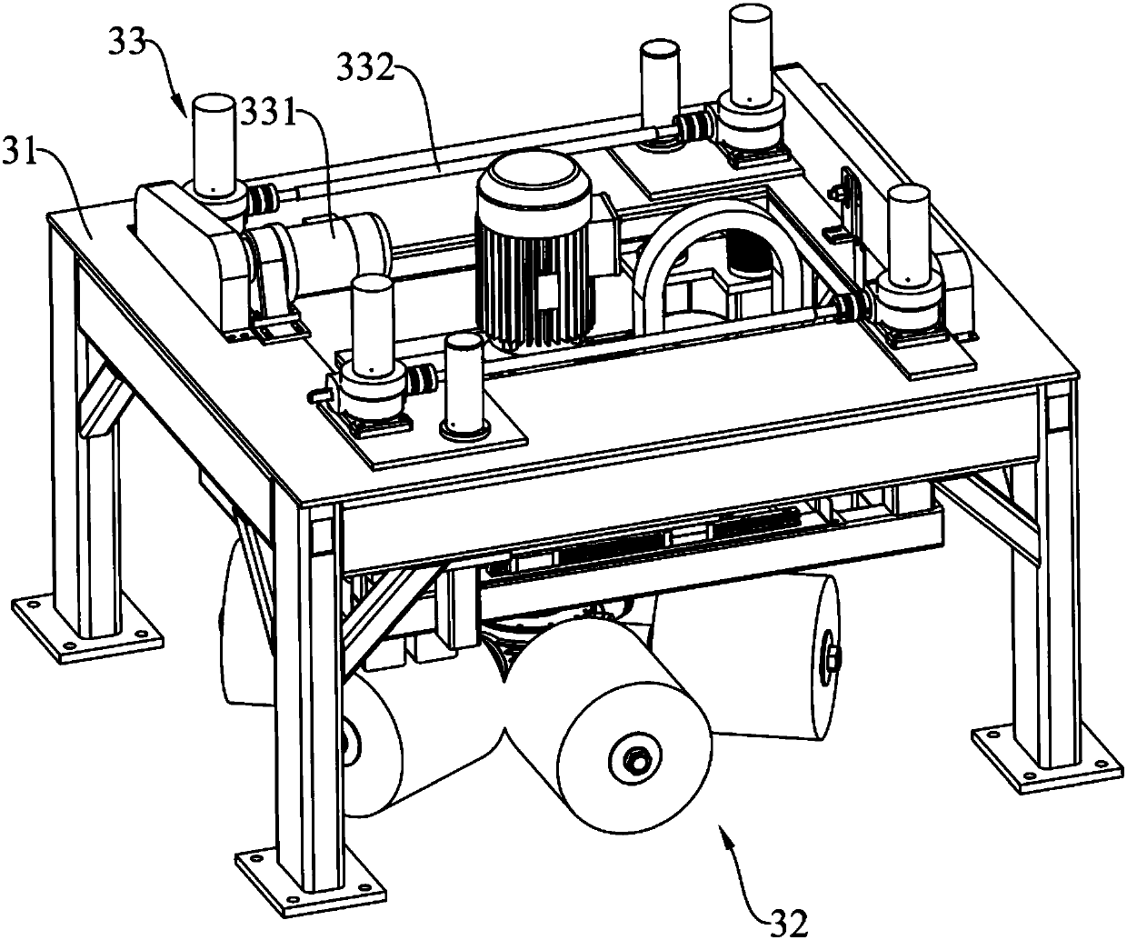
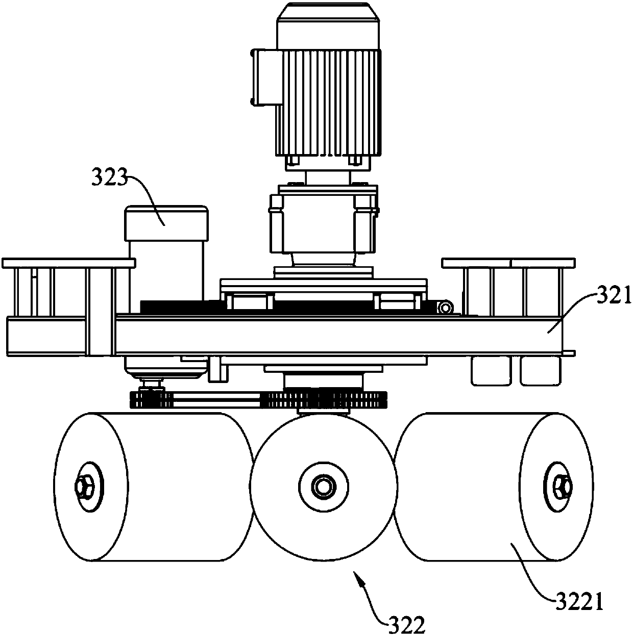
[0041] Such as figure 1 As shown, the deburring machine includes a machine base 1 and a conveying device 2 installed on the machine base 1, a universal roller brush grinding head 3, an abrasive belt grinding head 4 and a dust collection cover 5, wherein the conveying device 2 is used to convey the workpiece, the universal roller brush grinding head 3 and the abrasive belt grinding head 4 are located on the upper part of the conveying device 2 and arranged at intervals, and are used to grind the workpiece on the conveying device 2 to remove the workpiece Surface burrs, and processing of workpieces such as wire drawing, deslag removal and descaling. According to the actual needs of the workpiece to be processed, one or more universal roller brush grinding heads 3 and one or more abrasive belt grindin...


PUM


Abstract

The invention discloses a deburring machine, and belongs to the technical field of workpiece surface treatment. The deburring machine comprises a machine base, a conveying device used for conveying aworkpiece, a universal rolling brush grinding machine head used for deburring of edges and holes of the workpiece and an abrasive belt grinding machine head used for grinding the workpiece surface arearranged on the machine base, the universal rolling brush grinding machine head and the abrasive belt grinding machine head are sequentially arranged at an interval in the conveying direction of theconveying device, and the universal rolling brush grinding machine head and the abrasive belt grinding machine head are both located above the conveying device. Through combination of the universal rolling brush grinding machine head and the abrasive belt grinding machine head, the surface treatment machining procedure can be finished when the workpiece passes through the conveying device at a time, and the surface quality and the machining efficiency of the workpiece are improved.

Description

technical field [0001] The invention relates to the technical field of workpiece surface treatment, in particular to a deburring machine. Background technique [0002] The burr is mainly due to the plastic deformation of the material, which is a kind of redundant iron filings generated on the edge of the processed material, especially the material with good ductility or toughness, which is particularly prone to burrs, and the burr problem is still a problem in the metal processing industry so far. One of the unsolvable puzzles. [0003] In the field of metal processing, the most common method is manual deburring, using files, sandpaper, grinding heads, etc. as auxiliary tools to wipe off the burrs on the surface of the workpiece. This method consumes a lot of manpower and is inefficient; Due to the influence of manpower, it is difficult to control the weight of the hand. Excessive force will scratch the surface of the workpiece and affect the surface quality of the workpiec...

Claims


Application Information

Patent Timeline
IPC IPC(8): B24B21/00B24B27/033
CPCB24B21/002B24B27/033B24B29/005B24B7/06
Inventor 田志玉
Owner LANUSS LNDUSTRIAL EQUIP SUZHOU CO LTD
Learn More