Building wood board cutting-off device

A technology for cutting devices and wood boards, which is applied to wood processing equipment, forming/shaping machines, manufacturing tools, etc. It can solve the problems of not collecting cut sawdust, and the cutting machine cannot automatically return to its original position, so as to achieve the effect of easy recycling

Inactive Publication Date: 2018-03-30
钟晓芳
View PDF0 Cites 7 Cited by
  • Summary
  • Abstract
  • Description
  • Claims
  • Application Information

AI Technical Summary

Problems solved by technology

[0004] Aiming at the deficiencies of the prior art, the present invention provides a construction plank cutting device, which solves the problem that the existing cutting machine cannot automatically return to the original position and automatically stop working after cutting the plank, and does not have the function of collecting cut sawdust

Method used


Image

  • Building wood board cutting-off device
  • Building wood board cutting-off device
  • Building wood board cutting-off device

Examples


Embodiment 1

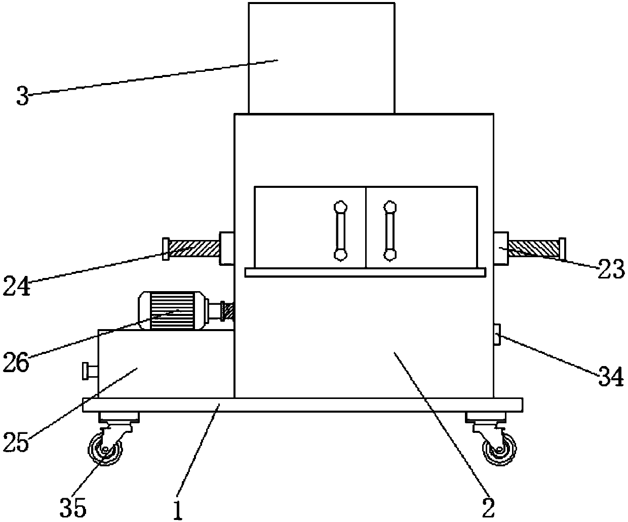
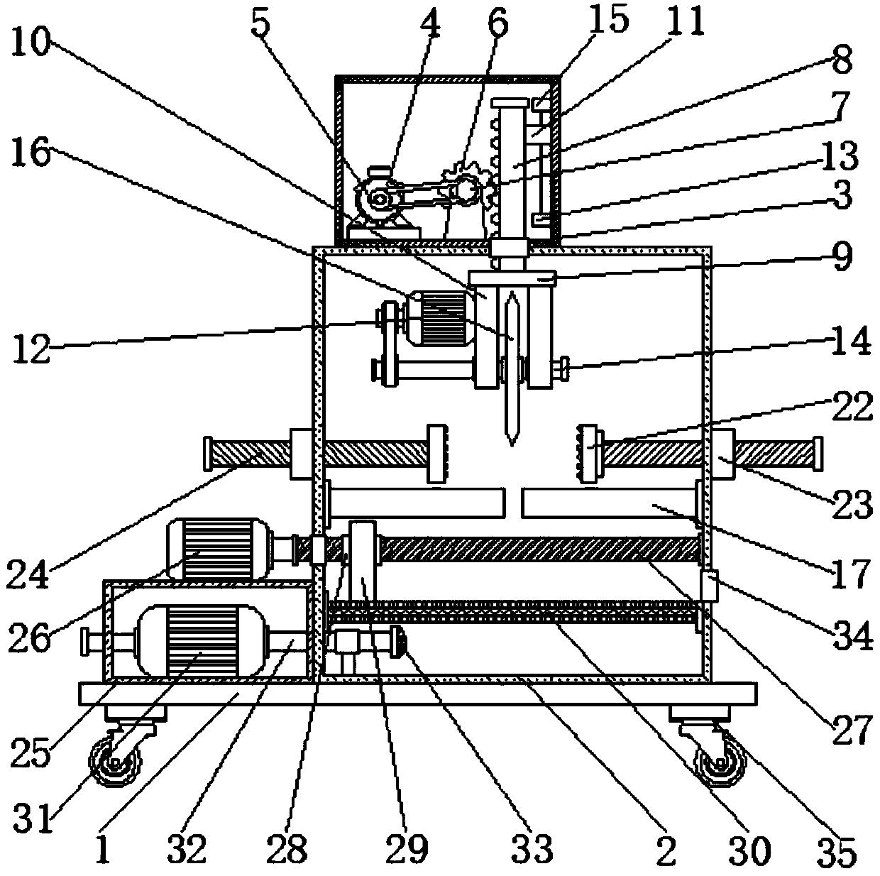
[0029] see Figure 1-2, a kind of building plank cutting device, comprises base 1 and box body 2, and cutting wheel 16 is installed on the top of box body 2 inner cavity, and fixing plate 17 is all fixed on the box body 2 inner wall of cutting wheel 16 both sides; Cutting wheel 16 and The moving parts are connected, and the moving parts take the cutting wheel 16 to move up and down. The moving parts include a motor box 3 and a first motor 4 , the motor box 3 is fixed on the top of the box body 2 , and the first motor 4 is fixed on the inner wall of the bottom of the motor box 3 . The outer surface of the output shaft of the first motor 4 is sheathed with the first pulley 5, the bottom of the motor case 3 inner wall and one side positioned at the first motor 4 are connected with a gear 6 through the support rod rotation, and the front of the gear 6 is fixedly connected with a second pulley. Pulley 7, the outer surface of the second pulley 7 is connected with the outer surface ...

Embodiment 2

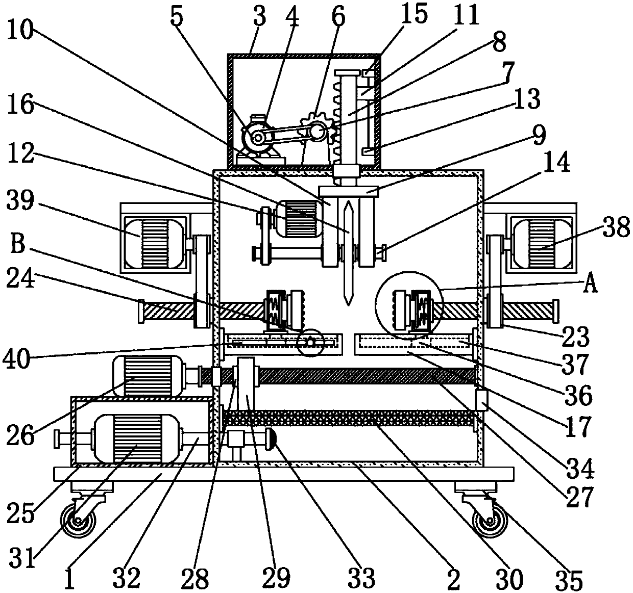
[0033] In addition to the technical features of Embodiment 1, the difference between this embodiment and Embodiment 1 is that: Please refer to Figure 3 ~ Figure 6 , the top of the fixed plate 17 is slidingly connected with a sliding frame 18, the sliding frame 18 is fixed with the clamping screw 24; one side of the sliding frame 18 is provided with a push rod 21, one end of the push rod 21 is fixed with the clamping block 22, and the other end penetrates into In the sliding frame 18, a first spring 20 is provided between the push rod 21 and the inner wall of the sliding frame 18; the fixed plate 17 is provided with a chute 37, and the lower end of the sliding frame 18 is fixed with a clamping sliding block 36 cooperating with the chute 37. Holding the sliding block 36 to slide in the chute 37 to realize the back and forth movement of the sliding frame 18. When the clamping block 22 clamps the plank to cut, the cutting wheel 16 will have a certain lateral vibration. Lateral v...


PUM


Abstract

The invention discloses a building plank cutting device, which comprises a base and a box body. A cutting wheel is installed above the inner cavity of the box. Fixed plates are fixed on the inner walls of the box on both sides of the cutting wheel; the cutting wheel is connected with a moving part, and the moving part It moves up and down with the cutting wheel; there is a clamping block that moves back and forth on the fixed plate, and the clamping block clamps the wooden board; there is a filter plate under the fixed plate, and a push block that can move back and forth is arranged above the filter plate. The invention relates to the technical field of building plank cutting equipment, and solves the problem that the existing cutting machine cannot automatically return to the original position and stop working after cutting the plank, and does not have the function of collecting cut sawdust.

Description

technical field [0001] The invention relates to the technical field of building board cutting equipment, in particular to a building board cutting device. Background technique [0002] Wooden boards are one of the important materials in the construction industry. Wooden boards are made of complete wood. They are durable and have natural textures. They are the best choice for decoration. Solid wood flooring is the most common type of decoration in recent years. Floor decoration material, as the name suggests, but due to the high cost of this type of board and the high requirements for construction technology, it is not used much in decoration. Among the wood boards, solid wood boards are the most common. Solid wood boards are generally classified according to the actual name of the board, and there is no uniform Standard. [0003] When using wood boards in construction, it is necessary to cut the wood boards. In the past, people used saws to cut the wood boards manually, but...

Claims


Application Information

Patent Timeline
Patent Type & Authority Applications(China)
IPC IPC(8): B27C5/02B27C5/06B27G3/00
CPCB27C5/02B27C5/06B27G3/00
Inventor 钟晓芳
Owner 钟晓芳
Why Eureka
Try Eureka