A drying tunnel device for a printing machine

A printing machine and drying tunnel technology, which is applied to the general parts of printing machinery, printing machines, printing and other directions, can solve the problems of unrecoverable printing parts, large space for drying tunnels, and high labor intensity, and achieves good heating effect. The effect of reducing floor space and reducing labor intensity

Active Publication Date: 2019-10-08
淮南晟莱水泵设备有限公司
View PDF6 Cites 0 Cited by
  • Summary
  • Abstract
  • Description
  • Claims
  • Application Information

AI Technical Summary

Problems solved by technology

[0002] The printing technology of the printing machine is to print the slurry on the surface of the fabric through the screen printing technology. The slurry used in this screen printing technology is liquid and is easy to deform after printing on the surface of the fabric. The fabric will not be stretched during use. As a result, the printed matter will fall off and cannot be restored, so the drying tunnel is used in the printing line. Since the current printing line is a straight line, generally the drying tunnel adopts a long and straight shape. This shape of the drying tunnel takes up a lot of space. If this kind of drying tunnel is placed in a limited factory building, other equipment cannot be placed, and this kind of drying tunnel is separated from the printing machine, requiring workers to remove the template on the printing machine and put it on the drying tunnel for baking, which is labor-intensive; the above Manufacturers who use the drying tunnel generally use electric heating wires to heat the drying tunnel. This heating method only makes the printed parts dry. When the fabric is in use, the printed parts will not recover or fall off due to stretching. Therefore, the invention It is necessary to use a drying tunnel device for printing machines to solve the above problems

Method used


Image

  • A drying tunnel device for a printing machine
  • A drying tunnel device for a printing machine
  • A drying tunnel device for a printing machine

Examples


Embodiment Construction

[0015] The following will clearly and completely describe the technical solutions in the embodiments of the present invention with reference to the accompanying drawings in the embodiments of the present invention. Obviously, the described embodiments are only some, not all, embodiments of the present invention. Based on the embodiments of the present invention, all other embodiments obtained by persons of ordinary skill in the art without making creative efforts belong to the protection scope of the present invention.

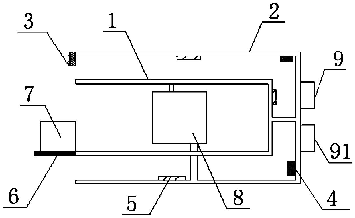
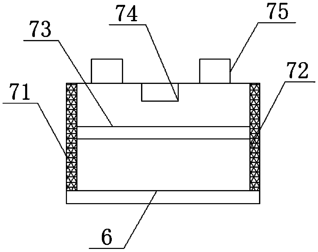
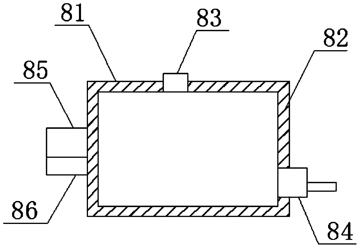
[0016] The present invention provides such Figure 1-3 A drying tunnel device for a printing machine is shown, which includes an inner tube 1, an outer tube 2 is provided on the outer side of the inner tube 1, a blower 3 is provided on one side of the outer tube 2, and a heat dissipation device is provided on the inner side of the outer tube 2. Fan 4, a temperature sensor 5 is uniformly arranged between the inner pipe 1 and the outer pipe 2, a ventilation plat...


PUM


Abstract

The invention discloses a drying tunnel device used for a printing machine. The drying tunnel device comprises an inner tube. An outer tube is arranged on the outer side of the inner tube. An air blower is arranged on one side of the outer tube. Cooling fans are arranged on the inner side of the outer tube. Temperature sensors are uniformly arranged between the inner tube and the outer tube. A ventilating plate is arranged on one side of the inner tube. Ventilating holes are uniformly formed in the surface of the ventilating plate. A ventilating device is arranged at the top of the ventilatingplate. A heating device is arranged at one side of the ventilating device. According to the drying tunnel device, by arranging the cooling fans and the air blower, the air flowing speed is increasedwhen fabric is heated between the inner tube and the outer tube, the heating speed is increased, a constant temperature is kept, gas is exhausted out of a drying tunnel, and in addition, the drying tunnel can be dehumidified; and by arranging the heating device, the inner tube and the outer tube can be heated through circulating heat transfer oil, the heating effect is good, the temperature is easy to control, meanwhile, the occupied area of the drying tunnel overall equipment is reduced, the drying quality for fabric printing is improved, and the labor intensity of workers is relieved.

Description

technical field [0001] The invention relates to the field of printing equipment, in particular to a drying tunnel device for a printing machine. Background technique [0002] The printing technology of the printing machine is to print the slurry on the surface of the fabric through the screen printing technology. The slurry used in this screen printing technology is liquid and is easy to deform after printing on the surface of the fabric. The fabric will not be stretched during use. As a result, the printed matter will fall off and cannot be restored, so the drying tunnel is used in the printing line. Since the current printing line is a straight line, generally the drying tunnel adopts a long and straight shape. This shape of the drying tunnel takes up a lot of space. If this kind of drying tunnel is placed in a limited factory building, other equipment cannot be placed, and this kind of drying tunnel is separated from the printing machine, requiring workers to remove the t...

Claims


Application Information

Patent Timeline
Patent Type & Authority Patents(China)
IPC IPC(8): B41F23/04
Inventor 欧家良
Owner 淮南晟莱水泵设备有限公司
Why Eureka
Try Eureka