[0028] In the following, the present invention will be further described through specific embodiments in conjunction with the accompanying drawings.
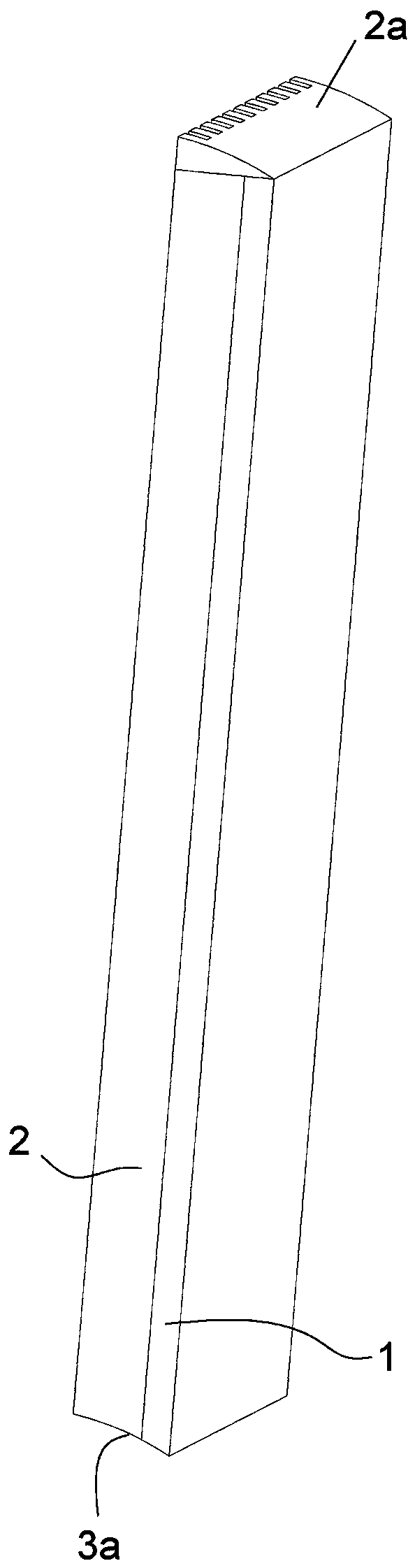
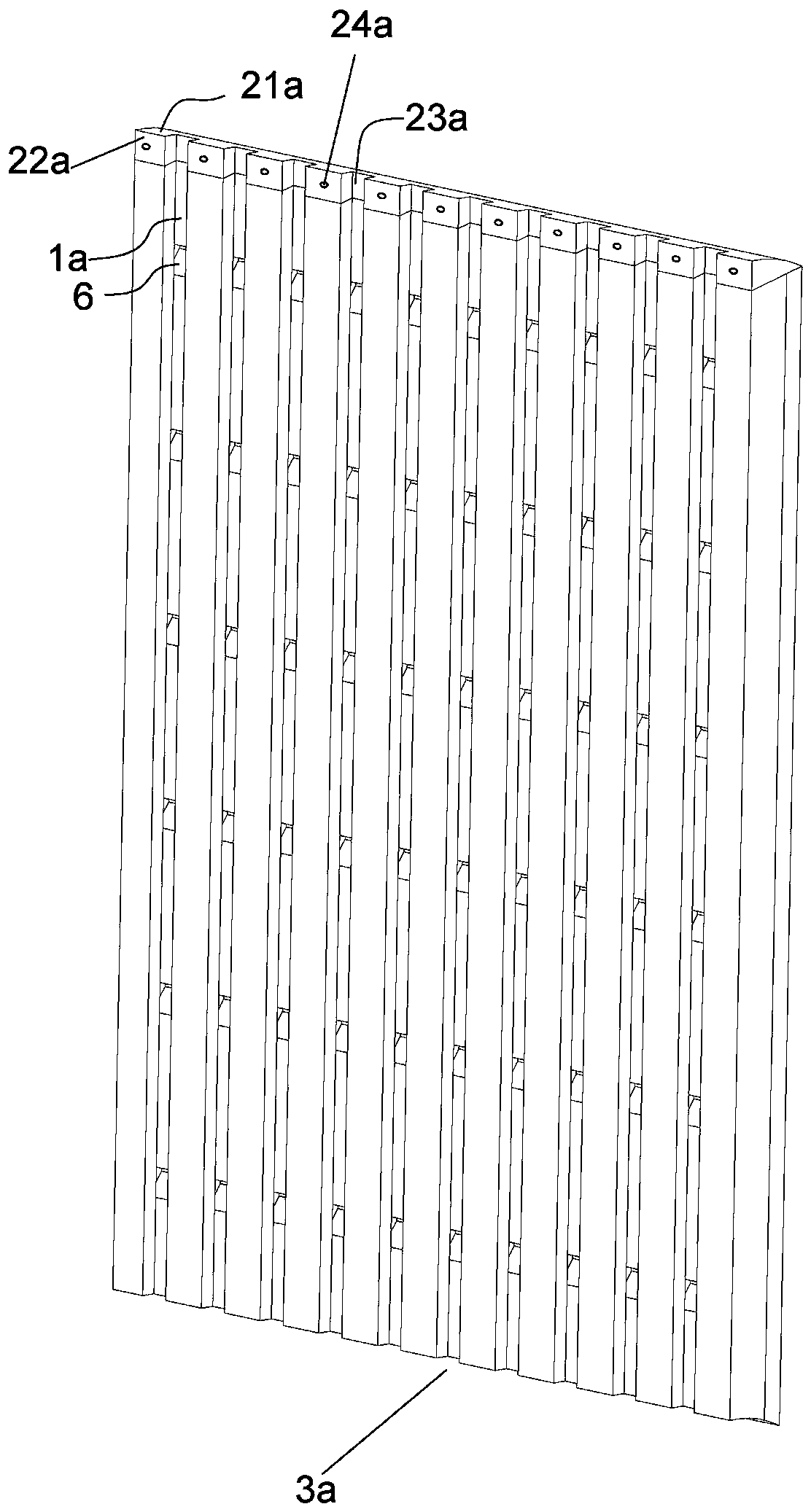
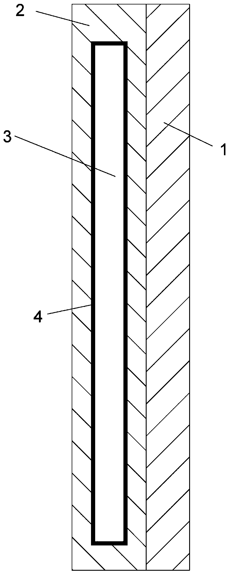
[0029] Such as Figure 1-6 As shown, a wall panel includes a decorative panel body 1 and a mounting substrate 2 connected to the decorative panel body 1. The mounting substrate 2 is attached to the wall and connected to the wall. The upper part of the mounting substrate 2 The end surface is provided with a downwardly extending heat dissipation cavity 3 with a square cross-section. A first heat conducting plate 4 is provided on the surrounding cavity walls and the cavity bottom of the heat dissipation cavity 3, and an electric heating device 5 is provided in the heat dissipation cavity 3 The heat dissipation cavity 3, the cavity wall close to the wall is provided with a plurality of heat dissipation holes 6, the heat dissipation holes 6 communicate with the side surface of the mounting substrate 2 close to the wall, and the number of heat dissipation holes 6 is determined according to the actual situation. To make a specific limitation, the first heat conducting plate 4 connected to the cavity wall with the heat dissipation hole 6 is correspondingly provided with a communication hole 8 communicating with the heat dissipation hole 6; the mounting substrate 2 is close to the wall A plurality of vertical drainage grooves 1a extending from top to bottom are opened on the side; the vertical drainage grooves 1a and the heat dissipation holes 6 intersect.
[0030] When a large amount of rainwater hits the wall and wall panels indoors, the rainwater generally penetrates gradually from top to bottom, and the wall penetration will be more severe, and as the rain continues to wet, the penetration range is wide. Adequate moisture can easily cause damage to the wall panels. In this embodiment, when rainwater hits the wall or the retaining wall, the rainwater is quickly guided to the ground through the vertical drainage groove 1a, which reduces the penetration rate of the wall from top to bottom. At the same time, the rainwater flows from the vertical Flowing through the drainage groove 1a will cause a certain amount of penetration to the wall corresponding to the vertical drainage groove 1a and the periphery of the wall. However, the penetration rate is relatively slow due to the rapid drainage of rainwater. In general, the vertical drainage groove 1a is provided, and the penetration range is small. At this time, through the electric heating device, heat is quickly generated, and the mounting substrate and the wall are heated through the heat conduction of the first heat conducting plate, and the dehumidification speed is fast. In addition, the heat dissipation in the heat dissipation cavity is further accelerated through the heat dissipation hole, and the wall is accelerated. The dehumidification also prevents safety accidents caused by the accumulation of heat in the heat dissipation cavity, increases safety performance, and improves the service life of the entire wall panel. In addition, due to the existence of the vertical drainage groove 1a, it can accelerate the flow of heat and improve the dehumidification efficiency .
[0031] Preferably, the heat dissipation hole 6 includes a horizontal heat dissipation channel 61 communicating with the heat dissipation cavity 3 and an oblique heat dissipation channel 62 connected to the horizontal heat dissipation channel 61 and extending diagonally downward. The vertical drainage grooves 1a meet. This arrangement prevents rainwater from quickly flowing through the vertical drainage groove 1a, entering the radiating cavity 3 from the radiating hole 6 and remaining in the electric heating device 5, and preventing the electric heating device 5 from burning when it is started.
[0032] Preferably, the wall panel in the present application further includes an anti-seepage top cover 2a for covering the top of the mounting substrate 2 and the decorative board body 1, and the anti-seepage top cover 2a includes a plastic block. This arrangement prevents rainwater from penetrating into the interior of the mounting substrate 2 from the upper end surface of the mounting substrate 2. The plastic block and the mounting substrate 2 can be connected in a snap-fit form through a snap-fitting piece, can also be connected in a plug-in form using a plug post, or can be connected by a double-sided glue.
[0033] The water-proof top cover 2a has an arc-shaped top surface 21a and a wall-fitting surface 22a for attaching to the wall; the arc-shaped top surface 21a is bent downward from the end close to the wall to the end away from the wall A plurality of vertical water guide grooves 23a are provided on the wall bonding surface 22a, and each vertical water guide groove 23a is correspondingly provided with a vertical drainage groove 1a and communicates with the vertical drainage groove 1a, and the wall is attached The surface 22a is also provided with a threading hole 24a for threading the electric heating device 5 through a wire, and a sealing ring is provided in the threading hole 24a. The seal ring is not shown in the drawings. Correspondingly, the bottom of the mounting base plate 2 and the decorative board body 1 is provided with a top cover matching groove 3a that matches the water seepage prevention top cover 2a. With this arrangement, on the one hand, the curved top surface 21a effectively prevents the gap between the upper and lower wall panels in the rainwater from flowing into the wall and enhances the waterproof effect. On the other hand, even if part of the rainwater flows into the wall along the gap, The rainwater is guided into the vertical drainage groove 1a by the vertical guide water trough 23a and then discharged, which improves the service life of the wall panel.
[0034] Preferably, the bottom of the mounting base plate 2 is provided with a top cover matching groove 3a that matches the water seepage prevention top cover 2a. This setting effectively prevents the gap between the upper and lower wall panels in the rain from flowing into the wall and improves the service life of the wall panels.
[0035] Preferably, the horizontal projection of the vertical drainage groove 1a falls into the horizontal projection of the vertical water guiding groove 23a. This arrangement ensures that when rainwater flows from the vertical water guide groove 23a to the vertical drainage groove 1a, it will not flow into the heat dissipation cavity 3 of the mounting substrate 2 from the connection between the two, which is beneficial to improve the service life of the wall panel.
[0036] Preferably, the horizontal heat dissipation channel 61 is provided with a water absorption layer 7 that allows hot air in the heat dissipation cavity 3 to pass through, and the water absorption layer 7 includes a sponge layer.
[0037] On the one hand, the sponge layer 7 has good water absorption performance. When the electric heating device 5 is not turned on, it can prevent moisture on the wall from entering the heat dissipation cavity 3 and remaining on the electric heating device 5, thereby causing the electric heating device 5 to encounter water Safety accidents such as burning will increase the safety performance and ensure the service life of the wall panels. Another convenience is that when the electric heating device 5 is turned on, the water on the sponge layer can evaporate, and the sponge layer after the water has evaporated restores its water absorption capacity. It can be recycled to improve the service life of the wall panel.
[0038] Preferably, the electric heating device 5 includes a mesh-shaped heating net 51, an upper mounting end 52 and a lower mounting end 53 respectively used to install the upper and lower ends of the heating net 51, and the upper end surface of the upper mounting end 52 is connected A sealing plate 53 for sealing the entrance of the heat dissipation cavity 3. The electric heating device 5 has a sealing plate 53 to prevent the heat in the radiating cavity 3 from being radiated from the entrance of the radiating cavity when the electric heating device 5 is started, so as to improve the utilization rate of heat and accelerate the dehumidification speed. Preferably, the upper end surface of the sealing plate 53 is flush with the upper end surface of the mounting substrate 2.
[0039] Preferably, the upper end surface of the mounting substrate 2 is further provided with a sunken mounting cavity 9 having the same cross-sectional shape as the heat dissipation cavity 3 for erecting the sealing plate 53. The level of the heat dissipation cavity 3 The projection falls into the horizontal projection of the sinking installation cavity 9. This arrangement ensures that the electric heating device 5 is conveniently and quickly installed on the mounting base plate, and only needs to be placed in the sinking mounting cavity 9.
[0040] Preferably, the sealing plate 53 includes a middle heat insulation plate 531, a second heat conduction plate 532 arranged adjacent to the periphery of the middle heat insulation plate 531, and the middle heat insulation plate 531 and the second heat conduction plate 532. On the outer heat insulation board 533 on the upper end surface, the second heat conducting board 532 is in contact with the first heat conducting board 4. With this arrangement, the outer heat insulation board 533 not only improves the utilization of heat, but also transfers heat through the first heat conducting plate 4 to the second heat conducting plate 532, and then transfers the heat to the inside of the surrounding mounting substrate to maximize heat transfer. Reasonable distribution, in other words, can ensure that most of the heat can be transferred to the wall through the first heat conducting plate 4 and the heat dissipation holes 6.
[0041] Preferably, the upper mounting end 52 and the lower mounting end 53 are both strip-shaped blocks.
[0042] Preferably, a fixing device 0 for fixing the lower mounting end 53 is provided on the first heat conducting plate 4 located at the bottom of the heat dissipating cavity 3; the fixing device 0 includes sides provided on both sides of the lower mounting end 53 The fixing block 01, the side surface of the side fixing block 01 close to the other side fixing block 01 is an inclined surface, and the inclined surfaces on the two side fixing blocks 01 form fixing openings whose openings gradually decrease from top to bottom. This arrangement further prevents the shaking of the electric heating device 5 and indirectly improves the service life of the wall panel.
[0043] The above-mentioned embodiments only describe the preferred embodiments of the present invention, and do not limit the concept and scope of the present invention. Without departing from the design concept of the present invention, various modifications and improvements made by those skilled in the art to the technical solution of the present invention should fall within the protection scope of the present invention. The technical content claimed by the present invention has been all It is stated in the claims.